Industrial Damper
Installation, Operation, and Maintenance Manual
D
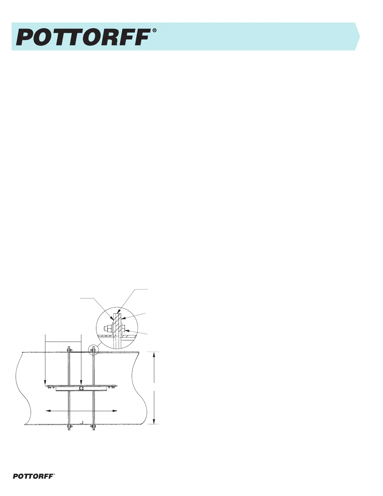
Duct by others
Damper
Flange
Air Flow is
Bi-Directional
D/2 + 0.25"
Gasket or Sealant
(By others)
Connecting Hardware
(By others)
Duct Mount Installation
Industrial Round Damper Installation
Figure 2
Industrial Damper IOM 2 of 4, February, 2024 pottorff.com
Do's
1. DO use provided lifting lugs.
2. DO install bolts into all supplied mounting holes, then tighten in an
even and staggered pattern to evenly compress the flange gasket (if
using).
3. DO check that the mating flange is flat, square, and parallel to the
damper flange.
4. DO check that damper blade(s) and linkages do not interfere with the
mating opening or duct when the damper is cycled between open
and closed positions.
Don'ts
1. DO NOT lift damper by blade(s).
2. DO NOT use actuator, linkage, or axles as lifting point.
3. DO NOT pry flanges to mate flange holes with opening or duct
flange as the frame could become warped, twisted, bent, or pulled
out-of-round causing binding.
4. DO NOT tighten mounting bolts by working around damper.
Please follow these instructions carefully. Failure to do so may void the
warranty. If the unit is supplied with an actuator, refer to the actuator
installation manual for details on the actuator before installation as well.
If the actuators were factory installed some adjustment may be required
after installation.
Start Up
Precautions should be taken before startup of the damper. All additional
safety accessories should be installed before starting the damper to
ensure the safety of everyone around. Rotate the blade(s) by hand to
ensure free movement of all components. Remove any construction
debris, loose hardware, tools, etc., from inside the damper and opening
or duct.
If electrical power is required, check all electrical connections before
turning on power. The supplied voltage must match the voltage required.
A qualified electrician must be used. Improper connections are hazardous
and can cause permanent damage to the electrical equipment.
If any NEMA electrical enclosure is supplied, use appropriate electrical
connections to maintain the NEMA rating. All wiring and fusing must
be in accordance with national electric code, local code, and project
specification requirements. If the unit is supplied with an actuator, refer to
the actuator installation manual for details on the actuator before startup
as well.
If pneumatic power is required, check all pneumatic connections. The
supplied pressures must match the pressures required. A qualified
technician must be used. Improper connections are hazardous and can
cause permanent damage to the pneumatic equipment. All plumbing
must be in accordance with national code, local code, and project
specification requirements. If the unit is supplied with an actuator, refer to
the actuator installation manual for details on the actuator before startup
as well.
Single Section Dampers
If the damper is supplied without mounting holes, drill or punch as
required. Pottorff is not responsible for corrosion around field punched or
drilled holes on painted dampers. Unless specifically designed for vertical
blades, the damper must be mounted with blade axis horizontal. Connect
the damper to the mounting location using the proper hardware. Attach
the damper to all connection points before tightening bolts. Confirm that
the damper is square, straight, and level, and free from bending, twisting,
or racking. Manually operate the damper to ensure that it operates freely.
Round Dampers
For round dampers, use appropriate gasketing (supplied by others)
between mating flanges. If the damper is supplied without mounting
holes, drill or punch as required. Pottorff is not responsible for corrosion
around field punch/drilled holes on painted dampers. Closed cell sponge
rubber, solid rubber, maximum 60 durometer is recommended.
Allow minimum of half of the blade diameter upstream or downstream,
plus 0.25" (6) for the blade seal material in the duct for blade rotation. The
damper can be mounted vertically or horizontally as a long axle is parallel
to the ground. Isolate damper from high vibratory loading. (See Figure 2)
Multi-Section Dampers
Follow instructions for single section dampers. Additionally, position
damper sections together in opening or duct. Align and match frame
markings or labels on adjacent sections. Fasten adjacent sections
together on front and back sides with screws or nuts and bolts. Shim
damper frame and opening or duct as required to prevent distortion of
frame. Multi-section dampers require bracing to support the weight of
the assembly and to hold against system pressure. Bracing should
support the damper horizontally, minimum 8 feet center-to-center. Large
vertical assemblies and high system pressure may require additional
bracing. All additional bracing and supports designed, supplied, and
installed by others.
 Loading...