Monitoring System
10-EN
After carrying out these checks, start up first the monitoring system and then the inverters.The system automatically
carries out ascan of theRS485 bus andautomaticallydetects the availableinverters.Thepresence of the inverters can be
checkeddirectlyfromthedisplay.
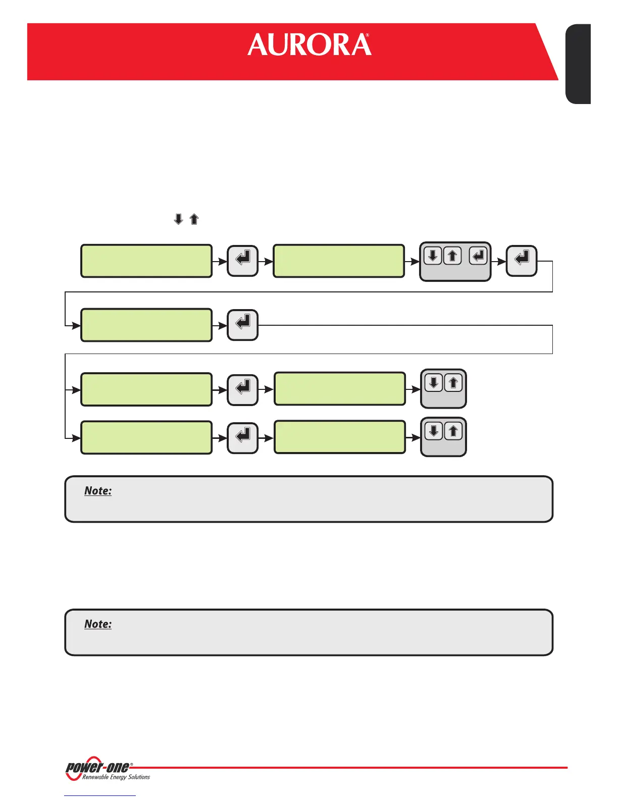
1. Enterthemainmenuasadministrator(Seepar.'B').
2. Accessthe'CURRENTVALUES'>'ENERGYINVERTERS'menu(todisplaythestringinverters)and/or'CURRENTVALUES'
> 'ENERGY RACK' (to display the 55kW conversion modules). The number of inverters detected during the scan will
be displayed;the list of the monitored inverters identified by the Serial Number (S/N) can be displayed by scrolling
usingthearrowkeys( ).
G. Configuration of the Analog Inputs
Theconnectionoftheanaloguesensorsmustbecarriedoutrespectingthepin-outsoftheJ3connector.
Thesystemhastwo0-10VdcinputsandaPT100/1000input.
CHANGE VALUE
NEXT
DIGIT
SET PIN TO 0010
PVI-AEC-EVO ......
12.00.00 01/01/11
>ENERGY INVERTERS
ENERGY RACK
menu pin
0***
30 INVERTERS
>INVERTER SN 123456
>CURRENT VALUE
SETTINGS
ENTER ENTER
ENTER
ENTER
CHANGE
INVERTER
>ENERGY RACK
ENERGY PLANT
RACK N. 1
>RACK SN 123456
ENTER
CHANGE
RACK
The time necessary for the PVI-AEC-EVO to scan and acquire the inverters depends on the number of
inverterspresentonthesameline(sometimesseveralminutes).
Toeachanalogue input (both0-10Vdc and PT100/1000types) itis possible to connect onlyone analog
sensor. Itisthereforenotpossibletoconnectmultiplesensorsonthesameanaloginput.
Withrespect tothe connection ofthe PT100/1000sensors,the system is abletocarry out the sensor reading throughthe
connectionofthree-wires:
Asensorpowersupplylinewhichisalsousedasasenseline(PT_ALIM);
A(return)readingline(PT_SENSE);
Apowersupplyclosingline(PT_RTN).
l
l
l
EN - ENGLISH
 Loading...