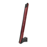
The provided manual describes the replacement procedure for the U-Channel on a Power-Pole Blade Shallow Water Anchor. The Power-Pole Blade is a marine accessory designed for shallow water anchoring, offering a swift, silent, and secure way to hold a boat in place. This particular manual focuses on the U-Channel, which can be either the upper or lower section of the anchor's structure.
Function Description:
The Power-Pole Blade Shallow Water Anchor is a hydraulic system that deploys a spike (Everflex™ spike) into the seabed to hold a boat stationary in shallow water. The U-Channel is a structural component of this anchor system, housing and guiding internal mechanisms. The replacement procedure detailed in the manual covers both the upper and lower U-Channels, indicating their critical role in the overall integrity and operation of the anchor. The Everflex™ spike, mentioned in the removal instructions, is the part that makes contact with the ground, providing the anchoring function. The system is designed to be deployed and retracted, allowing boaters to quickly and quietly secure their vessel without traditional anchors and ropes.
Important Technical Specifications:
The U-Channel replacement instructions are applicable to specific models of the Power-Pole Blade:
- 8' Models: Manufactured between 2012 and Mid-2019.
- 10' Models: Manufactured between 2012 and 2016.
This indicates that the design of the U-Channel and its attachment points may vary for models outside these ranges, or for newer versions. The manual specifies various tools required for the replacement, which also gives insight into the hardware used:
- Wrenches/Sockets: 9/16" and 1/2" sizes are needed, suggesting the use of corresponding nuts and bolts for assembly.
- Ratchet: For efficient tightening and loosening of fasteners.
- Spreader Block (Not Included): This is a crucial tool for both installation and removal of the U-Channel, particularly when connecting it to the Knuckle and Stern Bracket. Its necessity implies that the U-Channel components are under tension or require precise alignment during assembly, which the spreader block facilitates.
- 1/4" Flat Punch: Used for specific tasks during the removal or installation process, likely for driving out pins or aligning holes.
The "NOTICE: No mounting hardware is included in this kit" statement on page 1 is a key technical detail, informing users that they should not expect new bolts, nuts, or other fasteners with the U-Channel itself. This implies that existing hardware is expected to be reused unless damaged, or new hardware must be ordered separately.
Usage Features:
The manual primarily focuses on the maintenance aspect (replacement) rather than daily operational usage. However, some usage-related information can be inferred:
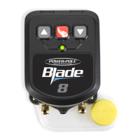
- Deployment Mechanism: The instruction "Lower the Power-Pole Anchor® down so the Everflex™ spike is about a foot off the ground" in Step 1 indicates that the anchor is a deployable system, likely controlled electronically or hydraulically from the boat.
- Component Interdependence: The diagrams on page 2 illustrate how various components like the Stabilizer Bar, Knuckle, Stern Bracket, Cylinder, and Cylinder End Cap are interconnected with the U-Channel. This highlights the modular design of the Power-Pole Blade, where individual parts can be serviced or replaced.
- Model-Specific Instructions: The diagrams specify which tools and procedures apply to "10' Models ONLY" or "Upper or Lower Replacement," indicating that there are subtle differences in the assembly and disassembly process depending on the specific anchor model and the U-Channel being replaced. For example, the Stabilizer Bar is only present on 10' models, and the Cylinder End Cap procedure is for "Upper Replacement ONLY."
Maintenance Features:
The manual is entirely a maintenance guide, providing detailed steps for replacing the U-Channel:
- Safety Precaution: "DO NOT touch the spike with bare hands" is a critical safety warning, suggesting potential hazards associated with the Everflex™ spike, such as sharp edges or hydraulic fluid.
- Step-by-Step Instructions: The process is broken down into clear steps:
- Step 1 (Preparation): Position the anchor correctly for access.
- Step 2 (Removal): Disassemble existing hardware. This step explicitly references diagrams (on the reverse side, i.e., page 2) for visual guidance.
- Step 3 (Installation): Install the new U-Channel, again referencing diagrams.
- Tool Requirements: A comprehensive list of necessary tools is provided, ensuring users are prepared before starting the procedure.
- Specialized Tool Requirement: The "IMPORTANT! A Spreader Block will be needed..." note emphasizes the necessity of a specific tool for proper installation and removal, indicating that certain components are under tension or require precise alignment. This tool is not included, so users must acquire it separately.
- Hardware Replacement Guidance: "IMPORTANT! Replace any hardware that is worn or damaged. Always replace nylon lock nuts." This is a crucial maintenance recommendation. Nylon lock nuts are designed for single-use to maintain secure fastening and prevent loosening due to vibration, so their mandatory replacement ensures the long-term reliability of the anchor.
- Ordering Replacement Parts: The inclusion of a QR Code A for ordering proper hardware (specifically for the Hardware Kit) streamlines the process of obtaining necessary replacement fasteners, reinforcing the importance of using correct and undamaged parts.
- Customer Support: Contact information (phone number and option) is prominently displayed on both pages, offering direct access to customer service for assistance, which is a valuable maintenance feature for users who encounter difficulties.
- Visual Aids: The diagrams on page 2 are essential maintenance features, providing visual representations of the components and the order of disassembly/assembly for different sections of the anchor (Stabilizer Bar, Knuckle, Stern Bracket, Cylinder With Stabilizer Bar, Cylinder End Cap). These diagrams are labeled with the specific tools required for each section (e.g., "9/16" Tools," "1/2" Tools"), further simplifying the process. The "Insert and Twist" instruction in Figure A on page 1 likely refers to a specific method of engaging or disengaging a component, which is clarified by the visual.
In summary, the manual provides a detailed, safety-conscious, and visually supported guide for replacing the U-Channel on specific Power-Pole Blade models, emphasizing the use of correct tools, proper hardware replacement, and readily available customer support.