Step 7: Programming Dual Units
NOTE: Anchors are preprogrammed as a single unit.
When using only one anchor, do not program as
a port or starboard.
Step 8: Continued
1. Using the “up” and “down” buttons on both HPUs,
determine which HPU controls the port side Power-Pole
anchor and which one controls the starboard side.
(Figure #10)
2. With both HPUs identified, begin with the starboard
side unit. Locate the “program” button on the top of the
HPU, and depress and hold it for 6 seconds until LED
flashes red and two chimes are heard followed by a
single beep.
3. Next, depress and release the “up” button for the
starboard side HPU. The LED will flash red 1 time
with a single beep indicating that the HPU has been
assigned as the starboard side unit. Press and release
the program button to save and exit. The LED will
flash red 1 time with a single beep followed by two
consecutive beeps.
4. On the port side, repeat Step 2 to enter programming
mode. Next, depress and release the down button
on the HPU. The LED will flash red twice with two
consecutive beeps indicating that the programming
has been completed successfully, and the HPU has
been assigned as the port side unit. Press and release
the program button to save and exit. The LED will
flash red 2 times with a double beep followed by two
consecutive beeps.
NOTE: For addition menu settings please refer to the
Owner Guide.
Program Button
Figure 10
Step 2: Mounting the Power-Pole
®
1. Transom mounting: The hydraulic tubing can be
routed through either side of the stern bracket.
(Figure #2A)
Adapter plate mounting: The hydraulic tubing can be
re-routed through the center of the stern bracket.
(Figure #2B)
NOTE: For ease of routing feed one line at a time.
BE SURE THERE ARE NO KINKS IN THE TUBING.
2. Once the tubing has been re-routed and the mounting
location has been selected, place the stern bracket
against the transom, and mark the mounting holes
with a fine point marker.
3. Drill a pilot hole into each of the four marked
locations with a 9/64” drill drill bit.
4. Apply a liberal amount of marine grade sealant
between the stern bracket and the hull, as well as
around the 5/16” holes.
5. With a 1/2” wrench and 1/2” socket, fasten the stern
bracket to the transom using (4) 5/16” x 3.5” all-
thread transom mount bolts
A
, (4) 5/16” neo-bond
washers
B
, (4) 5/16” fender washers
C
, and (4)
5/16” tall brass nuts
D
.
The rubber backed neo-bond washers
B
will protect
the powder coated surface of the stern bracket, and
they must not be over tightened. (Figure #3)
Step 3: Hydraulic Pump Unit (HPU)
Choose a mounting location
1. Locate a dry compartment in the vessel with ample
space to accommodate the HPU. The footprint of the
HPU is approximately 6.5”x 7”.
NOTE: Be sure to allow enough clearance
surrounding the HPU such that the hydraulic tubing
will not make a severe bend when exiting the
compartment. Also, allow enough space to install
the (2) 3/8” x 3/4” bolts
E
through the mounting
bracket and into the HPU.
Step 5: Installing Hydraulic Tubing
1. Guide the blue and black hydraulic tubing through the
black mesh tubing cover
M
.
NOTE: The black mesh tubing
M
cover may need to be
trimmed to length.
WARNING: Keep debris out of the hydraulic tubing. Use
the red end caps provided at all times while routing
the hydraulic tubing throughout the boat. Debris in the
tubing will cause damage to the HPU.
Step 5: Continued
2. The hydraulic tubing may be routed in one of two
ways. It may be routed either over the transom or
through the transom using the (2) supplied thru-hull
bushings
K
. If the hydraulic tubing is not being
installed through the transom, route the tubing to the
HPU as per your preference, and proceed to Number
4 below. If the hydraulic tubing is to be installed
through the transom, holes will need to be drilled for
the thru-hull bushings
K
.
NOTE: When choosing a location for the holes, ensure
that the tubing will form a natural curve when leaving
the stern bracket, and that the transom holes will be
above the water line.
3. Drill pilot holes in the transom with a 9/64” drill bit
for each of the (2) thru-hull bushings
K
. Then, drill out
both pilot holes with an 11/32” drill bit. Insert the (2)
thru-hull bushings
K
, and route the tubing to the HPU.
(Figure #2A)
Note: Be sure to allow an adequate amount of slack in
the hydraulic tubing between the stern bracket and the
point that the tubing enters the vessel. This will provide
slack in the hydraulic lines to allow for full up and
down operation.
4. Now trim the excess tubing with a razor. All cuts made
in the tubing must be as straight as possible to ensure
that the compression fittings do not leak.
Note: For ease of future maintenance, leave enough
excess hydraulic tubing such that the HPU can be
moved out of the compartment with the tubing still
attached.
5. While taking note of their location, remove the blue
and black dust caps from the hydraulic compression
fittings on the HPU.
6. Push the blue tubing into the compression fitting
labeled UP (blue dust cap), and the black tubing into
fitting labeled DN (black dust cap). While holding
the blue tubing fully inserted into its respective
compression fitting base, begin threading the
compression fitting nut onto the base. Repeat this step
for the black tubing. (Figures #5 & #6)
Note: The tubing needs to pass through the ferrule far
enough such that there is approximately a
1/2” length of tubing exposed. (Figure #5)
Step 8: Pairing Dual Units to a
Single Wireless Controller
NOTE: The Power-Pole comes paired to the included
Dash Switch and Key Fob remotes. When installing
dual units, you can program a single Dash Switch
and/or Key Fob remote to control both units.
To operate both units with one controller follow
Steps 1–4.
1.
Determine which unit is paired with the
controller by pressing the UP or DOWN button.
2. Locate the “program” button on the top of the HPU,
depress and hold it for 3 seconds until the LED turns
solid green in color and a single beep is heard.
3. Next, depress and release either the up or down
button on the switch. The green LED on the pump
unit will turn off and a single beep will confirm that
the pairing has been completed. The programming
light should now flash steadily green.
(Figure #11)
4. The switch is now paired to the pump units. Test by
pressing and holding the UP or DOWN button on
the controller until both units respond.
3. Use the “up” button on the HPU to retract the Power-
Pole anchor from the deployed position to the stowed
position. Keep the “up” button depressed for 10
seconds in order to bleed all residual air from the
hydraulic tubing. Repeat step 2 & 3 three times or until
satisfactory performance is achieved.
4. The HPU’s hydraulic fluid level may need to be topped-
off after the final priming has been completed.
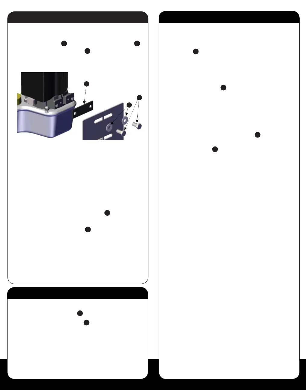
Step 4: Continued
5. Once the bracket is securely fastened, use a 9/16”
wrench to attach the HPU to its bracket using the (2)
3/8” x 3/4” bolts
E
, (2) 3/8” neo-bond washers
F
,
and (1) rubber pump gasket
i
.
(Figure #4.1 and 4.2)
6. Route the red wire to a 12 volt positive source via a
battery switch, and route the black wire to a 12 volt
negative source via a common ground post.
NOTICE: This HPU will draw current (40 mA)
from the battery source when not in use.
JL Marine Systems, Inc. strongly recommends
the use of a battery disconnect switch.
7. Once the wires have been trimmed to length with wire
cutters, install the (2) ring connectors
J
using wire
strippers and wire terminal crimpers.
8. Heat the (2) ring connectors
J
with a heat gun until
their respective jackets shrink completely and adhere
to the wires.
WARNING: DO NOT CONNECT the red or black wire
at this time. These wires will be connected once the
hydraulic tubing is installed.
Step 6: Priming the HPU
1. Now connect the red and black wires from the HPU to
their respective locations.
Once both wires are securely fastened, the green LED
on the HPU should flash indicating that the unit has
power.
2. Use the “down” button on the HPU to deploy the
Power-Pole anchor to the point where it makes
contact with a solid surface. Keep the “down” button
depressed for 10 seconds in order to bleed all residual
air from the hydraulic tubing. (Figure #9)
Figure 2A Side Routing
(for Transom Mounting)
Figure 2B Center Routing
(for Adaper Plate Mounting)
E
i
F
Figure 4.2
Figure 9
Program Button
Figure 11
A
A
B
B
C
D
Figure 3
H
Figure 4.1
Step 4: Installing the HPU
1. Remove the fill cap on the HPU, and fill the reservoir
to the “full” line with the supplied quart of
Green Marine
®
biodegradable hydraulic
fluid or an ISO 32 hydraulic fluid.
WARNING: Using anything other than an
ISO 32 hydraulic fluid, such as Green
Marine, may cause damage to the HPU,
and will void your warranty.
2. Place the HPU bracket in the
predetermined area of the vessel and
mark the four mounting hole locations with a fine point
marker.
WARNING: Before drilling holes to mount the HPU
mounting bracket, inspect the area beneath the
mounting surface to insure that the drill bit will not
cause any damage.
3. Drill a hole into each of the marked hole locations
with a 9/64” drill bit.
4. Fasten the bracket to the vessel using a #2 Phillips-
head screwdriver and the (4) #10 x 3/4” pan head
screws
H
.
Step 5: Continued
Figure 5 Figure 6
Figure 7
8. Tighten both compression fitting nuts with a 9/16”
wrench while simultaneously holding their respective
bases with a 1/2” wrench. (Figure #7)
Warning: The nuts must be tightened down far
enough such that none of the compression
fitting’s threads are visible; otherwise, hydraulic
failure may occur. (Figure #8)
 Loading...