STEP3
Installing The Hydraulic Pump Unit (HPU)
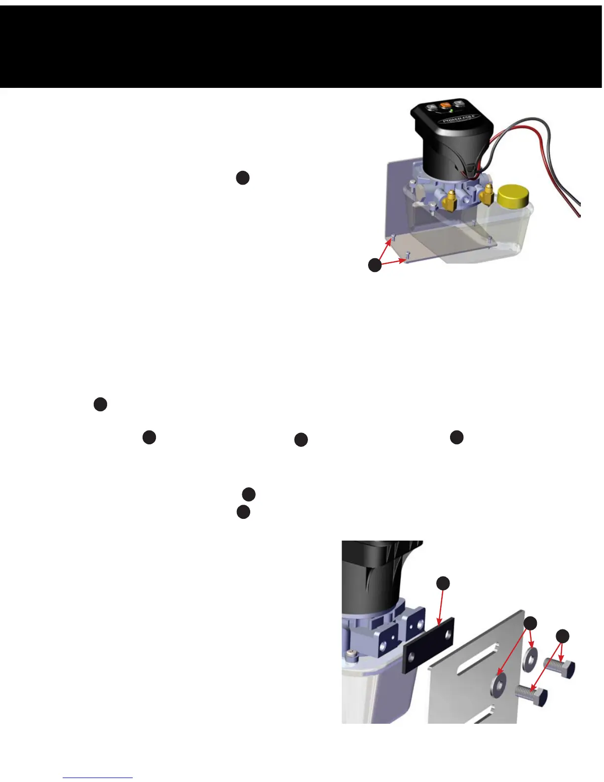
Figure 4
H
1. Locate a dry compartment in the vessel with ample space
to accommodate the HPU. The footprint of the HPU is
approximately 6.5”x 7”.
NOTE:
Be sure to allow enough clearance surrounding the HPU
to install the (2) 3/8” x 3/4” bolts
E
through the mounting
bracket and into the HPU.
2. Remove the fill cap on the HPU and fill the reservoir to the “full”
line with the supplied quart of Green Marine® biodegradable
hydraulic fluid.
WARNING: Using anything other than an ISO 32 hydraulic fluid,
such as Green Marine, may cause damage to the
HPU.
3. Place the HPU bracket in the predetermined area of the vessel and mark the (4) mounting hole locations
with a fine point marker.
WARNING: Before drilling holes to mount the HPU mounting bracket, inspect the area beneath the
mounting surface to ensure that the drill bit will not cause any damage.
4. Drill a hole into each of the marked hole locations with a 9/64” drill bit.
5. Fasten the bracket to the vessel using a #2 Phillips-head screwdriver and the (4) #10 x 3/4” pan head
screws
H
. FIG. 4
6. Once the bracket is securely fastened, use a 9/16” wrench to attach the HPU to its bracket using the (2)
3/8” x 3/4” bolts
E
, (2) 3/8” neo-bond washers
F
, and (1) rubber pump gasket
I
. FIG. 5
7. Route the red wire to a 12 Volt positive source via a battery switch to prevent power draw when not in use.
8. Route the black wire to the 12 Volt negative common ground post.
9. Install the (2) ring terminal connectors
J
using wire strippers and wire terminal crimpers.
10. Heat the (2) ring terminal connectors
J
with a heat gun until their respective jackets shrink completely and
adhere to the wires.
WARNING: DO NOT CONNECT the red or black wire to the
battery at this time. These wires will be connected
once the hydraulic hose is installed.
Figure 5
I
E
F
 Loading...