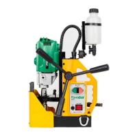
The Powerbor PB32 is a magnetic drilling machine designed for drilling holes in ferrous metals. Its primary function is to hold the drill securely in place using a magnet while drilling. This machine is suitable for use in various applications such as fabrication, construction, railways, and petrochemical industries where drilling into ferrous metals is required. Any use outside of its intended purpose will void the warranty. The machine is CE approved and comes with original instructions published in April 2019.
Technical Specifications
The Powerbor PB32 is available in two model numbers: 18A32/110 and 18A32/230, indicating different voltage configurations.
Motor Unit:
- Voltages: Available in 110V 50-60Hz and 230V 50-60Hz.
- Normal full load: 6.5 A (110V) / 3.2 A (230V), both delivering 720 W.
- Electro Magnet: 0.54 A (110V) / 0.26 A (230V), both consuming 60W.
- Holding Force: 10000N at 20°C with 25mm minimum plate thickness. The magnetic performance decreases with material thickness less than 25mm. In such cases, additional material should be positioned under the magnet or an alternative secure restraining method must be used.
- Total Load (magnet + motor): 780W for both 110V and 230V models.
Overall Dimensions:
- Height (minimum): 320mm
- Width (including Capstan fitting): 90mm
- Length Overall (including Guard): 260mm
- Nett Weight: 12.5 kgs
Performance:
- Maximum hole cutting capacity: 32mm diameter x 25mm deep in .2/.3C steel.
- Arbor bore: 19.05mm (3/4") diameter.
- Vibration total values (triax vector sum) in accordance with EN61029-1: Vibration emission value of 2.5 m/s².
- Level of sound pressure in accordance with EN61029-1: 86 dBA.
The machine is suitable only for a single-phase 50-60Hz A.C. power supply and must not be used on a D.C. supply. Using the magnetic drill on the same structure when arc welding is in progress is prohibited, as D.C. current can earth back through the magnet and cause irreparable damage. The appliance must be earthed, and any modifications will invalidate the guarantee.
Usage Features
Safety Precautions:
- Always read the instructions before operation.
- Disconnect power before any adjustments, servicing, or maintenance.
- Keep the work area clean, well-lit (500 Lux recommended), and free from flammable liquids or gases.
- Avoid body contact with earthed surfaces to prevent electric shock; a high-sensitivity (30 mA/0.1s) residual current device (RCD) is recommended.
- Keep untrained persons and children away from the work area.
- Store idle tools in a dry, locked-up place, out of reach of children.
- Do not force the machine; it performs better and safer at its intended rate.
- Use the right tool for the job.
- Dress properly: avoid loose clothing or jewelry, wear non-skid footwear, and use protective hair covering.
- Wear safety glasses, ear defenders/plugs, face/dust masks, and protective gloves.
- Maintain a safe operating distance from swarf and the cutting area.
- Ensure dust extraction equipment is properly connected and used.
- Do not abuse the cord; keep it away from heat, oil, and sharp edges.
- Secure work with clamps or a vice.
- Maintain proper footing and balance.
- Keep cutting tools sharp and clean.
- Regularly check the machine for wear or damage.
- Disconnect tools when not in use, before servicing, or when changing accessories.
- Ensure keys and adjusting wrenches are removed before turning on.
- Ensure the magnet is OFF before plugging in.
- Use outdoor-approved extension leads for outdoor use.
- Be aware of vibration emissions, which can vary based on usage.
- Stay alert and do not operate the tool when tired or under the influence of alcohol or illegal substances.
- Check for damaged or missing parts before use.
- Only use recommended accessories.
- Repairs should be carried out by a qualified Powerbor technician using original spare parts.
- Never operate with missing or damaged parts.
- Do not direct water or flammable liquids over the drill.
- The operator must be physically capable of handling the machine's weight and trained in its use.
Operational Safety Procedures:
- Ensure the magnet is OFF before plugging in.
- Do not use in wet or damp conditions or in the presence of flammable liquids/gases.
- Inspect all electrical cables before activation.
- Use only approved extension cables.
- Check all operational systems, switches, and magnet function before use.
- Securely restrain the machine to a fixed independent feature (e.g., with safety strap RD4329B) to prevent free movement if the magnet detaches.
- Always wear approved eye protectors, ear defenders, and recommended PPE.
- Disconnect from power when changing cutters or working on the machine.
- Protect hands when changing cutters or removing swarf.
- Ensure cutter-retaining screws are secured tightly.
- Regularly clear the work area and magnet base of swarf and dirt.
- Remove ties, rings, watches, and loose adornments.
- Securely enclose long hair.
- If the cutter gets stuck, stop the motor immediately, disconnect power, and turn the arbor to and fro; do not attempt to free the cutter by switching the motor on/off.
- If dropped, thoroughly examine the machine for damage before resuming drilling.
- When operating inverted, use minimal coolant and ensure it does not enter the motor unit.
- Position the guard over the cutter before activation.
- Do not operate the machine as the ejected slug may cause injury.
- Store the machine in a safe, secure location when not in use.
- Ensure approved Powerbor™ agents conduct repairs.
Operating Instructions:
- Keep the inside of the cutter clear of swarf.
- Ensure the coolant bottle has sufficient cutting oil; occasionally depress the pilot to ensure correct metering.
- Follow control panel instructions to start the machine.
- Always switch off the motor using the MOTOR stop button, not the MAGNET switch.
- Apply light pressure when starting a cut until the cutter enters the work surface, then increase pressure to load the motor. Excessive pressure is undesirable and can trigger the safety overload protection device.
- Ensure the slug from the previous hole has been ejected before cutting the next. If a slug sticks, move the machine to a flat surface, switch on the magnet, and gently bring the cutter down to make contact to straighten and eject it.
- Apply a small amount of light oil lubricant regularly to the slide and arbor support bearing.
- Cutter breakage is often due to insecure anchorage, a loose slide, or a worn arbor support bearing.
- Only use approved cutting fluid.
Mounting Cutters:
- The machine accepts cutters with 19.05mm (3/4") dia. Weldon shanks.
- Lay the machine on its side with feed handles uppermost, and wind the arbor down to its lowest point.
- Place the appropriate pilot through the hole in the cutter shank.
- Insert the cutter shank into the arbor bore, aligning the two drive flats with the socket screws.
- Tighten both screws using a hexagon key.
Fitting the Chuck:
- To replace the arbor with a drill chuck, first remove the arbor using the supplied spanners.
- Place one spanner on the motor's output shaft.
- Turn clockwise until it contacts the dovetail slide.
- Place the second spanner on the arbor flats and apply clockwise pressure. Magnetizing the base can help hold the machine.
- If the arbor is tight, tap the spanner with a soft mallet.
- Once unscrewed, remove the arbor support bracket by removing its two socket cap head screws.
- Screw the chuck into place.
- To refit the arbor, reverse this process.
Maintenance Features
To ensure optimal performance and longevity, regular maintenance is crucial. Always disconnect the power supply before performing any maintenance.
Maintenance Schedule:
- Every operation:
- Visual check of machine for damage.
- Check operation of machine.
- Check magnetic base.
- 1 week (or more frequently if used often):
- 1 Month:
- Check grease.
- Check armature.
Detailed Maintenance Steps:
- Visually check the machine for damage: Before each operation, inspect the machine for any signs of damage, especially the mains cable. Do not use a damaged machine, as it could cause injury or death.
- Check operation of the machine: Ensure all components are working correctly.
- Machine Brushes: Check weekly (or more frequently with heavy use) for abnormal wear. Replace brushes if they are worn more than 2/3 of their original length to prevent machine damage.
- Magnetic base: Before every operation, ensure the magnetic base is flat and undamaged. An uneven base will reduce holding efficiency and could cause injury.
- Check machine grease: Check gearbox grease monthly to ensure all moving components are covered. Change the grease at least once a year for best performance.
- Check Armature of the machine: Check monthly for visual signs of damage to the body or commutator. Some wear on the commutator is normal, but any abnormal damage requires replacement.
Troubleshooting
The manual provides a comprehensive troubleshooting guide for common issues:
- Magnet and motor do not function: Check power supply connection, wiring, magnet switch, and control unit.
- Magnet functions, motor does not: Check wiring, carbon brushes (stuck or worn), magnet switch, on/off switch, control unit, armature, and field.
- Magnet does not function, motor does: Check magnet and control unit.
- Hole cutters break quickly, holes are bigger than the hole cutter: Check for play in the guide, bent spindle, bent shaft, or bent pilot.
- Motor running roughly and/or seizing up: Check for bent spindle or shaft, or a triangular guide not mounted straight.
- Motor making a rattling sound: Check for worn gear ring, worn gears, or lack of grease in the gearbox.
- Motor humming, big sparks, and no force: Check for damaged armature, burned field, or worn carbon brushes.
- Motor does not start or fails: Check for damaged wiring, armature, field coil, or brushes.
- Insufficient magnetic force: Check for damaged wiring, clean and dry magnet bottom, flat work piece, bare metal contact, work piece thickness (too thin), defective control unit, or defective magnet.
- Frame under voltage: Check for damaged wiring or defective magnet, or a seriously dirty motor.
- Fuse blows when magnet switch is turned on: Check for damaged wiring, wrong fuse value, defective magnet switch, control unit, or magnet.
- Fuse blows when motor is started up: Check for damaged wiring, motor running roughly, defective armature/field, worn carbon brushes, or defective control unit.
- Rotation system free stroke too long: Check for loose or defective gear-rack or defective rotation system.
Cutter Selection
The manual includes a table for cutter selection based on material and hardness:
| Material |
Material Hardness |
Cutter |
| Mild and free cutting steels |
<700N/mm² |
M2 |
| Mild and free cutting steels |
<850N/mm² |
M42 |
| Steel angle and joists |
<700N/mm² |
M2 |
| Steel angle and joists |
<850N/mm² |
M42 |
| Plate and sheet steel |
<700N/mm² |
M2 |
| Plate and sheet steel |
<850N/mm² |
M42 |
| Aluminium |
<750Nmm² |
M2 |
| Aluminium |
<850N/mm² |
M42 |
| Brass |
<700N/mm² |
M2 |
| Brass |
<850N/mm² |
M42 |
| Cast iron |
<700N/mm² |
M2 |
| Cast iron |
<850N/mm² |
M42 |
| Stainless steel |
<700N/mm² |
M2 |
| Stainless steel |
<850N/mm² |
M42 |
| Stainless steel |
>850N/mm² |
TCT |
| Rail track |
>850N/mm² |
M42 |
| Tool steel |
>850N/mm² |
TCT |
| Die Steel |
>850N/mm² |
TCT |
Warranty
Powerbor™ warrants its machines against faulty materials under normal usage for 12 months from the initial purchase date. All other parts (excluding cutters) are warranted for 90 days, provided the warranty registration card (or online registration) is completed and returned within 30 days of purchase. Failure to do so will void the warranty. Powerbor™ will repair or replace faulty items at its option.
The warranty does not cover:
- Components subject to natural wear and tear from use not in accordance with instructions.
- Defects caused by non-compliance with operating instructions, improper use, abnormal environmental conditions, inappropriate operating conditions, overload, or insufficient servicing/maintenance.
- Defects caused by using accessories, components, or spare parts other than original Powerbor™ parts.
- Tools with changes or additions.
- Electrical components are subject to the manufacturer's warranty.
Warranty claims must be logged within the warranty period, requiring submission of the complete tool with the original sales receipt indicating the purchase date. A complaint form must also be submitted. Defective goods must be returned pre-paid to Powerbor™. Powerbor® is not liable for subsequent direct or indirect loss or damage. This warranty is in lieu of any other warranty, expressed or implied, including merchantability or fitness for a particular purpose. Powerbor™ reserves the right to make improvements and modifications without prior notice.