www.powerbox-systems.com 3
Features
• Optical separation between the receiving system and the ignition system
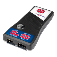
• External LED switch status indicator
• Regulated (6.0V) or pass-through output voltage
• RPM monitor for all current telemetry systems
• Telemetry function for PowerBox, Jeti, Futaba, Graupner, Multiplex, Spektrum, JR
• Failsafe mode
• Machined aluminium heat-sink
• Compact, low-prole format
1. CONNECTIONS
The connections are clearly labeled on the SparkSwitch RS; the following descri-
bes them in detail:
PWM/BUS:
The PWM socket is not needed if you are using a PowerBox, Jeti, Futaba or Spek-
trum radio control system, as the SparkSwitch RS receives its switching informa-
tion directly via the telemetry servo bus. By default the SparkSwitch RS is set to
channel 12 for switching the ignition on and off. With these systems all you have to
do is connect the unit to the receiver using a patch lead.
All other systems require two patch leads: one connection to switch the SparkS-
witch, and one for the telemetry.
• PowerBox P²-BUS: connect the BUS input to the P²-BUS on the receiver
• Jeti Ex-BUS: connect the BUS input to an EX-BUS output on the receiver
• Futaba S.BUS2: connect the BUS input to S.BUS2 on the receiver
 Loading...