www.powerbox-systems.com 5
2. SETTINGS AT THE TRANSMITTER
You must assign a dedicated channel at the transmitter for switching the ignition
switch. The travel of the switched channel at the transmitter should be -100% to
+100%; the switching threshold is located at around +50%.
If you are using a system which supplies the switching signal via the telemetry
bus (PowerBox, Jeti, Futaba and Spektrum), the simplest method is to use chan-
nel 12, as this is the default setting on the SparkSwitch RS.
If this channel does not conform to your preferred transmitter layout, you can ch-
ange the channel from the transmitter if you are a PowerBox (Telemetry menu) or
Jeti (JetiBox MX) user. If you use a Futaba or Spektrum system, you can change
the channel using PowerBox Terminal and the USB Interface.
If you are using a Multiplex, Graupner or JR system, simply connect the PWM
output to the assigned channel at the receiver.
No other settings have to be changed, as the SparkSwitch RS detects the teleme-
try system automatically.
3. INSTALLATION
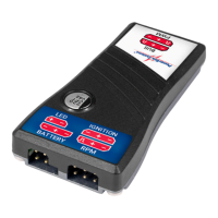
Install the SparkSwitch RS close to the ignition unit. Under no circumstances in-
stall the unit close to the receiver. The cables to the ignition unit should be as short
as possible, and should not be bundled together with other cables which feed into
the receiving system - such as the throttle servo lead.
In contrast, the cables to the receiver can be any length you like, as they are “clean”
thanks to the optical isolation from the ignition system.

 Loading...