12
S T E P
3
Be careful to assemble all components in the
sequence they are presented.
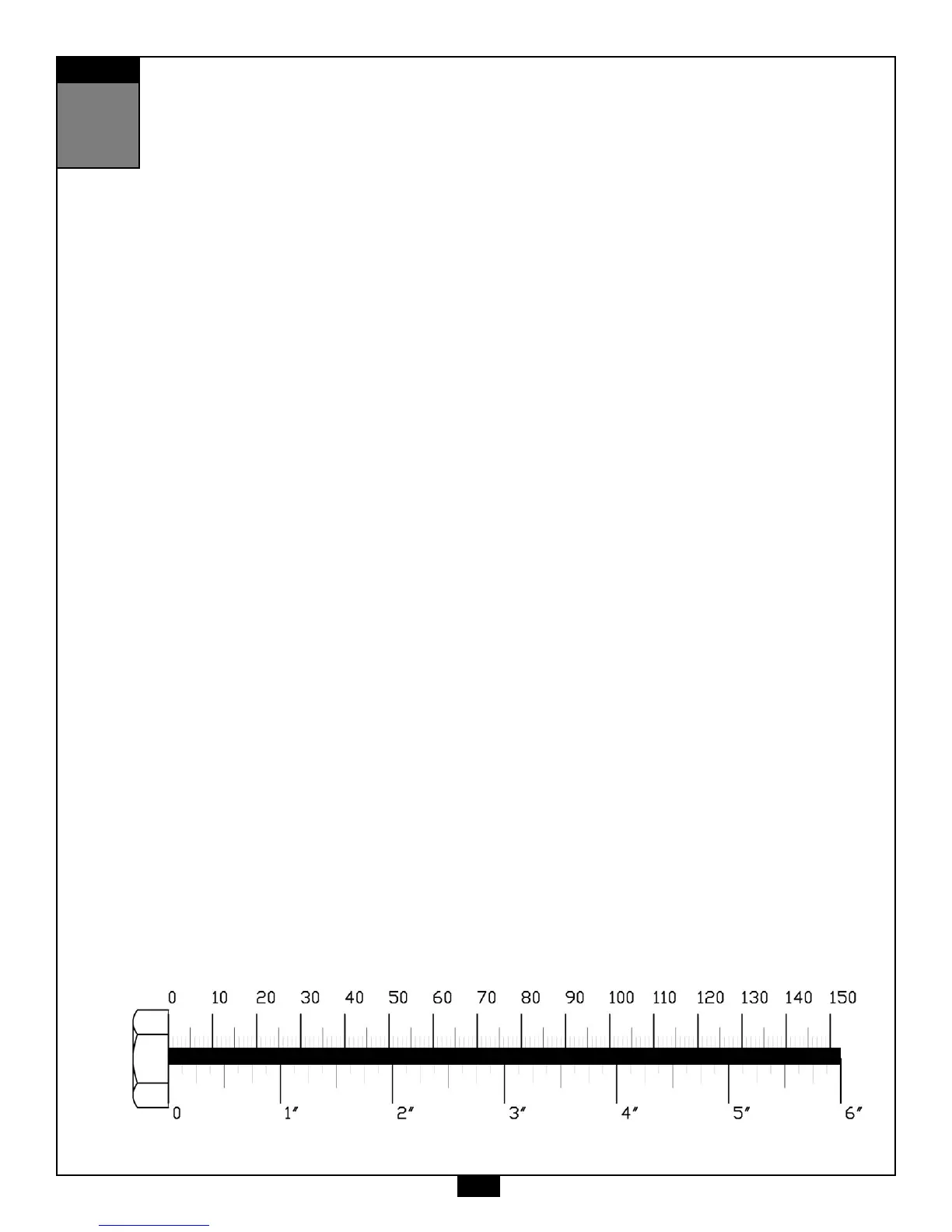
Inch
MM
A. Insert Plastic Bushing (93) into the Lower Main Frame (A) as shown.
Insert Front Foot Plate (J) into the Plastic Bushing (93) in the Lower Main Frame (A) as shown and attach
using:
Two 52 (3/8” x 3 3/4” hex head bolt)
Four 60 (3/8” washer)
Two 70 (3/8” washer)
B. Attach End Cap (50)* to Front Foot Plate (J) as shown.
*NOTE:
These parts might be pre-installed.
C. Attach Leg Extension Arm (K) to the Lower Main Frame (A) as shown using:
Two 38 (5/16” x 1/2” allen head bolt)
Two 61 (5/16” washer)
D. Attach two End Caps (17)* to the top and bottom of Leg Extension Arm (K) as shown.
*NOTE:
These parts might be pre-installed.
E. Attach End Cap (17)* to Lower Main Frame (A) as shown.
*NOTE:
These parts might be pre-installed.
G. You can now wrench tighten all bolts and nuts in this step.
Leave all pulley bolts hand tight until cable installation in step 10 is completed.
 Loading...