Be careful to assemble all components in the
sequence they are presented.
S T E P
7
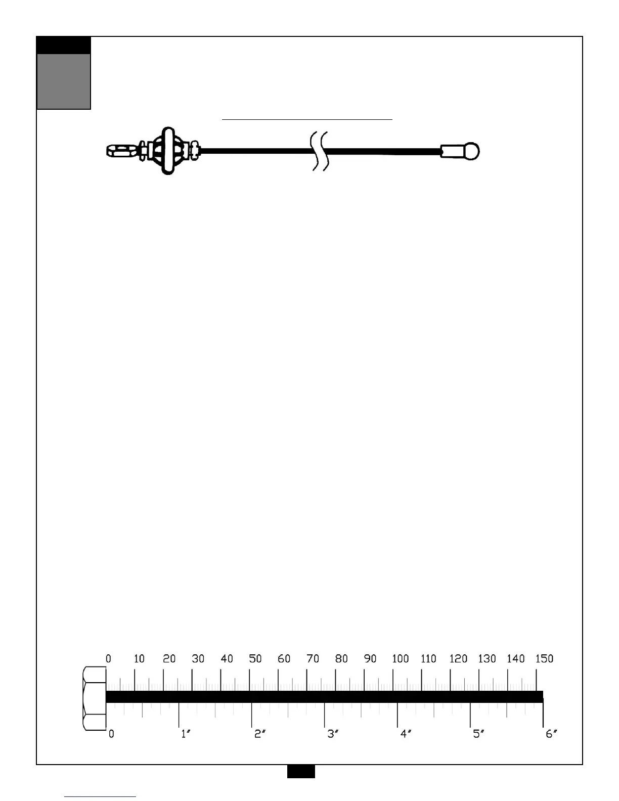
Inch
MM
High Pulley Cable (90)
Ball Stop End
Metal Ball End
Note:
All Pulleys in this step are 4 1/4” diameter, except where noted in step 7B and 7C.
Leave all pulley bolts hand tight until step 10 is completed.
A. See diagram 1. Begin at the high pulley station. Route the metal ball end of the High Pulley Cable (90)
up and through the opening where Pulley (A1) will be installed and then down through the next
opening where Pulley (A2) will be installed.
B. See diagram 2. Install 3 1/2” diameter Pulley (A1) under Cable (90) and into Upper Main Frame (D) as
shown using:
One 52 (3/8” x 3 3/4” hex head bolt)
Two 14 (pulley spacer)
One 70 (3/8” nylon lock nut)
C. See diagram 2. Install 3 1/2” diameter Pulley (A2) under Cable (90) and into Upper Main Frame (D) as
shown using:
One 52 (3/8” x 3 3/4” hex head bolt)
Two 14 (pulley spacer)
One 70 (3/8” nylon lock nut)
D. See diagram 1. Route Cable (90) over the top and around pre-installed Pulley (A3) as shown.
Route Cable (90) around Pulley (A4) and install Pulley (A4) into Upper Main Frame (D) as shown in
diagram 2 using:
One 52 (3/8” x 3 3/4” hex head bolt)
Two 14 (pulley spacer)
One 70 (3/8” nylon lock nut)
E. See diagram 1. Route Cable (90) between Pulley (A3) and pre-installed Pulley (A5).
Route Cable (90) over the top and around Pulley (A5) and back through Frame (D).
Route Cable (90) down through the small arm sticking out of the Upper Main Frame (D).
And pull entire length of Cable through.
F. See Diagram 2. Install Pulley (A6) under Cable (90) and into arm sticking out of the Upper Main
Frame (D) using:
One 54 (3/8” x 2” hex head bolt)
Two 84 (pulley spacer)
One 70 (3/8” nylon lock nut)
Cable (90) should be hanging down through the bottom of the small arm sticking out of the
Upper Main Frame (D).
G. See Diagram 2. Attach Press Arm Pulley Shroud (U) to Press Arm Pivot (Q) as shown and tighten.
20
 Loading...