Be careful to assemble all components in the
sequence they are presented.
Inch
MM
Note:
All Pulleys in this step are 4 1/4” diameter, except where noted in step 9C.
Leave all pulley bolts hand tight until step 10 is completed.
A. See Diagram 1. Route Cable (91) up and through Upper Floating Pulley Bracket (V).
Route Cable (91) around Pulley (B5) and install Pulley (B5) using:
One 54 (3/8” x 2” hex head bolt)
Two 60 (3/8” washer)
One 70 (3/8” nylon lock nut)
B. See Diagram 1. Route Cable (91) through Leg Press Pulley Bracket (W).
Route Cable (91) around Pulley (B6) and install Pulley (B6) using:
One 54 (3/8” x 2” hex head bolt)
Two 60 (3/8” washer)
One 70 (3/8” nylon lock nut)
C. See Diagram 1. Insert Cable (91) through Upper Main Frame (D) and install 3 1/2” diameter Pulley (B7)
under Cable (91) as shown using:
One 52 (3/8” x 3 3/4” hex head bolt)
Two 14 (nylon bushing)
One 70 (3/8” nylon lock nut)
D. See Diagram 1A. Attach Short Cable (92) to Lower Main Base Frame (A) using:
One 52 (3/8” x 3 3/4” hex head bolt)
One 60 (3/8” washer)
One 70 (3/8” nylon lock nut)
E. See Diagram 1A. Attach the other end of Cable (92) to the hook on the bottom of Leg Press Pulley
Bracket (W).
G. You can now wrench tighten all bolts and nuts. Do NOT re-tighten any of the pad bolts.
S T E P
10
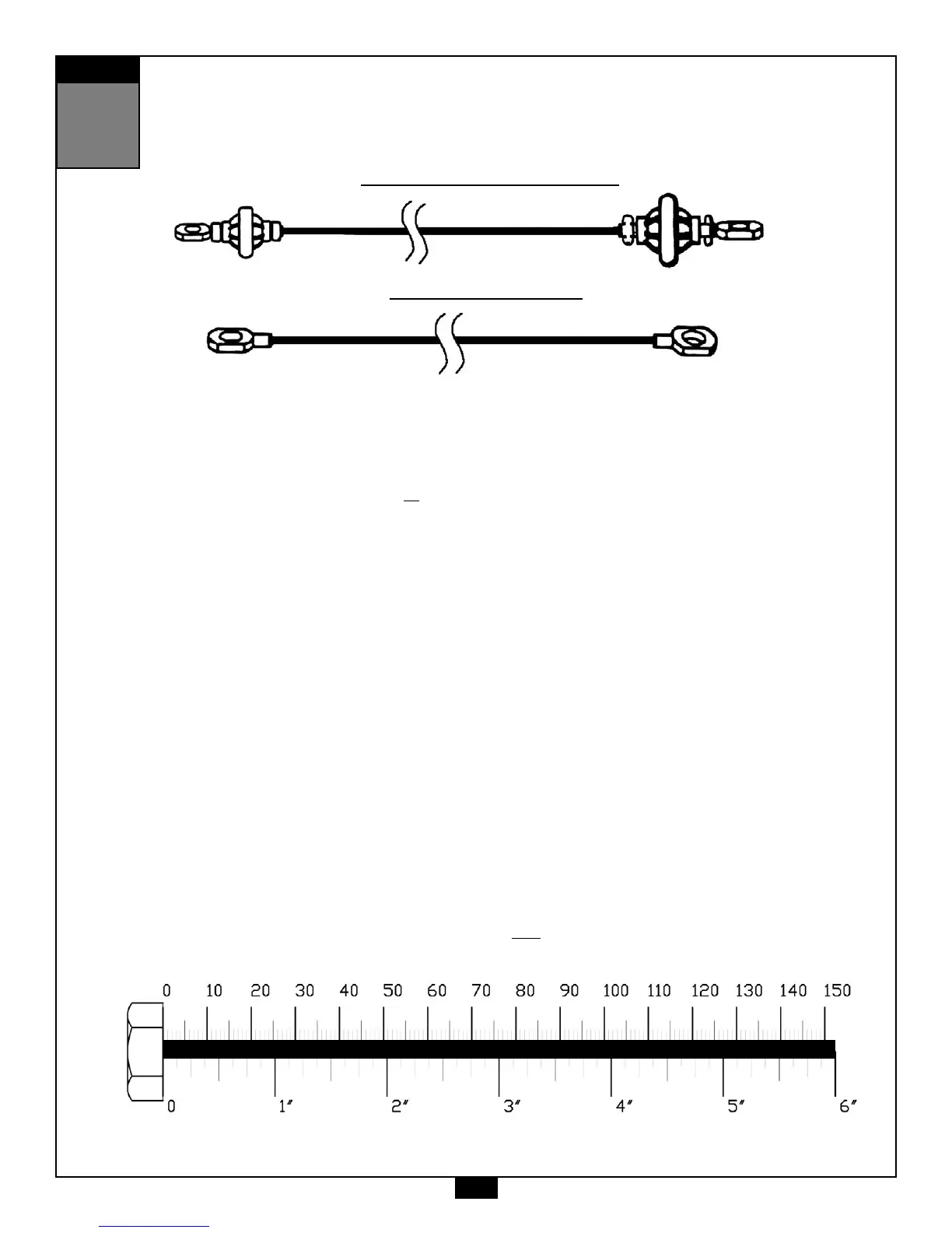
Ball Stop End
Small Ball End
Stamped Eye End
Stamped Eye End
Low Pulley Cable (91)
Short Cable (92)
26
 Loading...