18
S T E P
7
Be careful to assemble all components in the
sequence they are presented.
Inch
MM
NOTE:
Finger tighten all hardware in this step. Do NOT wrench tighten until the end of step 7.
Note:
Pulleys in this step are 4 1/4” diameter, except where noted in step 7B.
Leave all pulley bolts hand tight until step 7 is completed.
A. See diagram 1. Route Cable (19) around Pulley (A4) and install Pulley (A4) into the Main Frame (A)
as shown in diagram 2 using:
One 24 (3/8” x 2 1/2” hex head bolt)
Two 18 (pulley bushing)
One 40 (3/8” nylon lock nut)
B. See diagram 1. Route Cable (19) around 3 1/2” Pulley (A5) and install 3 1/2” Pulley (A5) into the top
pulley flange in Pivot Arm (F) as shown in diagram 2 using:
One 23 (3/8” x 2” hex head bolt)
Two 32 (3/8” washer)
One 40 (3/8” nylon lock nut)
C. See diagram 1A. Route Cable (19) under the Main Frame (A) and connect to Main Frame (A) with a
Snap Link (6).
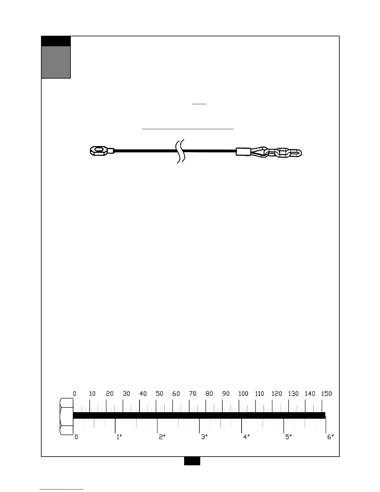
Leg Press Cable (19)
Stamped Eye End
Chain End