Be careful to assemble all components in the
sequence they are presented.
S T E P
1
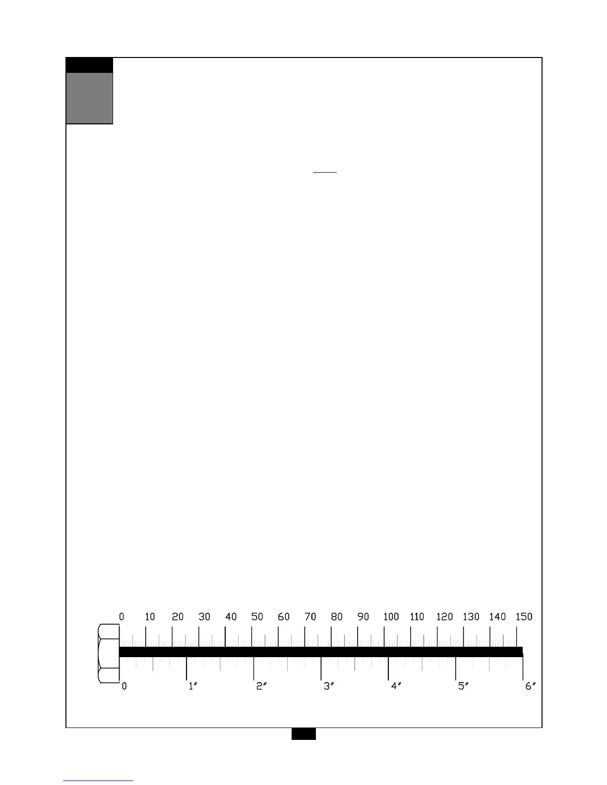
Inch
MM
NOTE:
Finger tighten all hardware in this step. Do NOT wrench tighten until the end of step 7.
6
A. Attach two Base Plates (B) to the Main Frame (A) as shown using:
Two 25 (3/8” x 4” hex head bolt)
Four 32 (3/8” washer)
Two 40 (3/8” nylon lock nut)
B. Attach End Cap (1) to the front of Main Frame (A) as shown.
C. Attach Rubber Stop (11)* and Lock Nut (41)* into Main Frame (A) as shown.
*NOTE:
These parts might be pre-installed.