Owner’s Manual for Portable Generator 5
Section 2 General Information and Setup
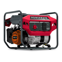
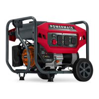
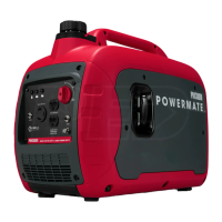
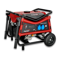
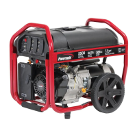
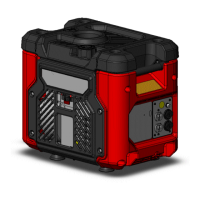
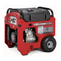
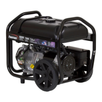
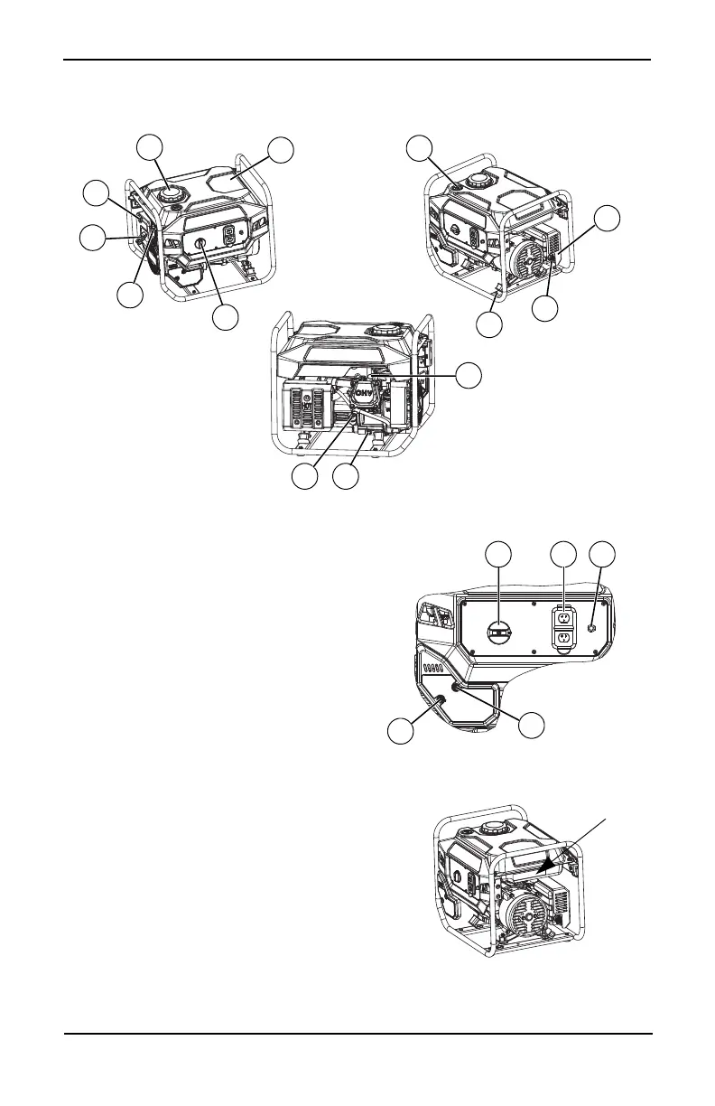
Figure 2-1. Features and Controls
Generator Components
Figure 2-2. Control Panel
Figure 2-3. Unit Identification Label
12
11
5
4
13
14
9
10
009407 009408
009412
7
6
3
15
8
1 120 Volt AC, 20 Amp, Duplex Receptacle
(NEMA 5-20R)
2 Circuit Breakers (AC)
3Oil Drain
4 Air Filter
5 Fuel Tank
6 Grounding Lug
7 Off/Run/Cold Start Dial
8 Muffler
9Gas Cap
10 Fuel Gauge
11 Oil Check/Fill
12 Spark Plug
13 Recoil Starter
14 Fuel Shut Off
15 Spark Arrestor
16 CO-SENSE RED (Hazard) (if equipped)
17 CO-SENSE YELLOW (Fault) (if equipped)