EasyManua.ls Logo

PowerNet V001 User Manual

PowerNet V001
8 pages
To Next Page IconTo Next Page
Page #1 background imageLoading...
Page #1 background image
V001 | VOLLEYBALL STATION
WWW.POWERNETINC.NETPOWERNET@POWERNET_BASEBALL POWERNETBASEBALLNET
13626 MONTE VISTA AVE UNIT F•CHINO•CA•91710 • 951.203.5495
Building confidence through sports is a far-reaching achievement that takes time and repetition.
Winners aren’t built overnight. We believe the people who challenge themselves and others to create
strong habits to excel in sports walk away with something even greater than the game; pride, confidence
and self-respect. This places them in a position to experience sustained success in all areas. Our dedication
to providing quality equipment at affordable prices has never wavered. Our commitment to getting our
gear in the hands of the player continues to be our driving force. Our hope is to play a role in building
winners not only in sports, but in life as well. We trust in the process of training and hard work on and
off the field
Out Work!
Out Play!
Thank you for choosing Powernet Inc.
Our Vision
Out Work! Out Play!
Other Items Available:
Barrier Net
*Comes in 4 sizes
Question and Answer IconNeed help?

Do you have a question about the PowerNet V001 and is the answer not in the manual?

PowerNet V001 Specifications

General IconGeneral
BrandPowerNet
ModelV001
CategorySports & Outdoors
LanguageEnglish

Summary

Our Vision

Setup Locations and Part Identification

Front Left Side of Frame

Designates location A on the net frame for setup.

Back Left Side of Frame

Designates location B on the net frame for setup.

Front Right Side of Frame

Designates location C on the net frame for setup.

Back Right Side of Frame

Designates location D on the net frame for setup.

Left Large Net Sleeve

Designates location E1 for the large net sleeve.

Right Large Net Sleeve

Designates location E2 for the large net sleeve.

Left Small Net Sleeve

Designates location F1 for the small net sleeve.

Right Small Net Sleeve

Designates location F2 for the small net sleeve.

Assembly Instructions: Base Frame and Poles

Step 1: Unfold Base Frame

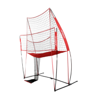
Unfold the base frame to widen the center frame for stability.

Step 2: Secure Base Frame Legs

Open base frame legs until button snaps into place on both sides.

Step 3: Insert Lower Poles

Insert lower poles into base frame post holders at locations B and D.

Step 4a: Feed Upper Back Pole

Feed one upper back pole through a large net sleeve (E1 or E2).

Step 4b: Loop Large Net

Loop the large net over the silver notch of the upper back poles.

Step 5: Connect and Raise Poles

Connect lower poles to upper poles and raise them into base frame holders.

Assembly Instructions: Net Securing and Finalization

Step 6: Secure Velcro Straps

Secure the velcro straps located at frame points A, B, C, and D.

Step 7: Insert Lower Poles

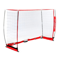
Insert lower poles into post holders located at frame points A and C.

Step 8: Feed Front Upper Pole

Feed a front upper pole through the small net sleeve (F1 or F2).

Step 9: Attach Small Net

Loop small net over front upper pole and attach to lower pole holder.

Warning

Use adult supervision and follow instructions. Frequent use/abuse may cause breakage.

Related product manuals