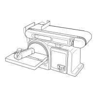
SQUARE THE TABLE
Refer to Figure 7
To ensure accurate end sanding, the work table must be
square to the sanding surfaces prior to using the work
table for disc sanding.
To check:
• Place combination square on the table with the ruler
side against the sanding disc. The table should be 90°
to the sanding disc.
• If the table is not 90° to the sanding disc, loosen the
adjustment knob and tilt table up and down until it is 90°
to the sanding disc. Tighten adjustment knob securely.
Recheck adjustment using the combination square.
Figure 7
Sanding Disc
Combination
Square
Work Table
Adjustment
Knob
SQUARE THE WORK SUPPORT
Refer to Figure 8
When using the sander belt in the horizontal position
the work support must be square to the sanding belt to
prevent the workpiece from being carried along the belt.
• Ensure the belt is tight and belt tension lever is closed.
Refer to Adjust The Drive Belt paragraph under
Maintenance.
• Place the combination square on the belt with the ruler
against the work support.
• Loosen the two hex screws securing the work support.
Adjust the work support to the square and tighten the
hex screws.
Figure 8
Combination
Square
Hex Screws
Work
Support
REPLACE THE SANDING DISC
Refer to Figure 9
• Remove the work table in reverse order of assembly.
Refer to Mount the Work Table paragraph in this
section.
• Remove Phillips head screw and locking washer
securing guard disc.
4
ASSEMBLY
• Remove the used sanding disc from the sanding disc
plate and dispose of properly
• Wipe the sanding disc plate clean.
• Peel the backing from the new sanding disc. Align the
new sanding disc with sanding disc plate and press
firmly into position. Ensure all edges are secure.
• Replace disc guard as shown, align holes and fasten
in place with Phillips head screw and locking washer.
Tighten securely.
Figure 9
4” x 36”
Sanding
Disc
Plate
Disc Guard
Phillips Head
Screw
Locking Washer
Sanding Disc
REPLACE THE SANDING BELT
Refer to Figure 10
• Use hex wrench supplied to loosen the bed locking
screw. Raise the sanding bed to 45° and tighten the bed
locking screw.
• Swing the belt tension lever open to release the belt
tension.
• Remove the used sanding belt and dispose of properly.
• Locate the directional arrow on the smooth side of the
sanding belt.
• Slide the new sanding belt over the idler pulley and
driving drum with the directional arrow pointing towards
the dust chute.
• Center the belt correctly on idler pulley and driving
drum.
• Close the tension lever to tighten the belt tension.
• Loosen the bed locking screw. Lower the bed to a
horizontal position and tighten the bed locking screw.
Figure 10
Idler Pulley
Tension Lever
Directional Arrow
Driving Drum
Bed Locking
Screw
Sanding Belt
Dust Chute
Hex Wrench