Chapter 4 Main circuit and terminal wiring
10
4-2. Instruction of soft starter terminal wiring.
Output terminal like Figure 4.2 illustration:
1
2
3
4
5
6
7
8
9
10
11
12
-
+
Bypass
output
Programming
output
Fault
output
7.Instantaneous
stop
start
public
Analog output
13
14
Communication
terminal
485+
485-
Figure 4.2
4-2-1.Terminal 1, 2 is bypass output which is used to control bypass contactor. Normally
open terminalwill close.The terminal capacity is AC 250V/5A.
4-2-2.Terminal 3, 4 is programable relay output, output model and function set by
“PE”parameter. This terminal is normally open passsive pot. Capacity is AC 250V/5A.
4-2-3.Terminal 5, 6 is error output: Which will colse when soft starter error or power lose.
Capacity is AC250V/5A.
4-2-4.Terminal 7 is transient stop input. This terminal must connect with terminal 10 when
soft starter normally work. If Terminal 7 disconnect with terminal 10, softstart will transient stop
and show error. This terminal can be controled by normal close output terminal of outside
protection device, set PA to 0 (primary protection),this terminal funtion is prohibited.
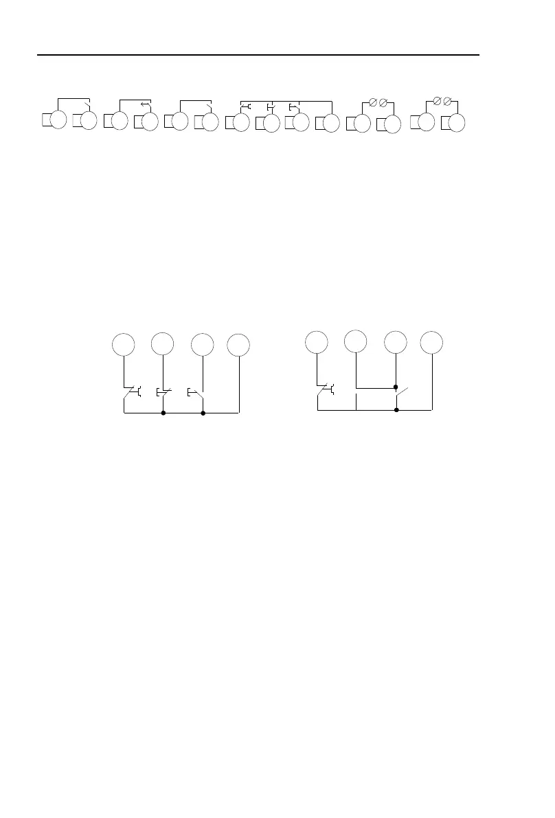
4-2-5.Terminal 8, 9, 10 is for wiring of outside control start,stop button. There are two type
wiring way(3 lines and 2 lines) to choose proper way according to demand. As Figure 4.3.
7
8
9
10
Transient
stop
stop
start
common
3lines way
7
8
9
10
Transient
stop
stop
start
common
2lines way:close K start
open K stop
K
Figure 4.3
4-2-6.Terminal 11, 12 is 0~20ma, 4~20ma DC anolog output. Which is used to inspect the
motor current. The max 20ma indicates motor current is 4 times of soft starter rated current. Which
can be viewed by extra 0~20ma, 4~20ma current meter. The max resistor of output load is 300Ω.
Remark: The machine defaults to 4 ~ 20ma output, if need 0 ~ 20ma output please explain in order.
4-2-7.Terminal 13, 14 for the RS485 communication terminal, 13 for the communication
terminal“485-”, 14 for the communication terminal “485+”.
4-2-8.The outside terminal should be correct connection, otherwise which will damage this
softstarter.
4-2-9.PR5200series soft starter main circuit diagram.
 Loading...