This document describes the PPA DZ BRUTALLE sliding gate operator, a device designed for automating sliding gates. It provides comprehensive information on installation, operation, and maintenance.
Function Description
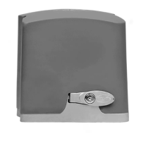
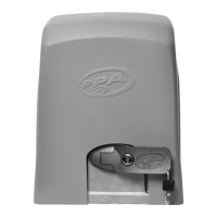
The PPA DZ BRUTALLE is a robust sliding gate operator designed to automate the opening and closing of gates. It is suitable for both residential and commercial applications, offering reliable and efficient gate operation. The system includes a motor, control board, and various safety and operational features to ensure smooth and secure gate movement. The operator is designed for easy installation and includes provisions for various accessories such as photocells and push buttons to enhance functionality and safety.
Important Technical Specifications
The DZ BRUTALLE operator comes in two main models, DZ BRUTALLE 3.0T (212) and DZ BRUTALLE 2.0T (217), with variations for different gate weights and lengths.
DZ BRUTALLE 3.0T (212) - Sliding Gate Operator:
- Model: JetFlex
- Rated Voltage: 127V / 220V
- Nominal Frequency: 60 Hz
- Rated Power: 200W / 150W
- Engine Rotation: 5800 RPM
- Nominal Chain: 1.7 A / 1.4 A
- Reduction: 1:50
- Linear Speed: Z12 = 26.3 m/min, Z17 = 37.2 m/min
- Maneuvers: 150 cycles/h
- Degree of Protection: IPX4
- Temperature Range: -5°C / +50°C
- Type of Insulation: Class B, 130°C
- Limit Switch: Hybrid (analog / digital)
- Max. Mass from the Leaf: Z12 = 3000 kg (661 lbs), Z17 = 2500 kg (551 lbs)
- Max. Dimension of the Gate: HEIGHT = 2.5 m, LENGTH = 3.0 m
DZ BRUTALLE 2.0T (217) - Sliding Gate Operator:
- Model: JetFlex
- Rated Voltage: 127V / 220V
- Nominal Frequency: 60 Hz
- Rated Power: 200W / 180W
- Engine Rotation: 5800 RPM
- Nominal Chain: 1.8 A / 1.6 A
- Reduction: 1:50
- Linear Speed: Z12 = 26.3 m/min, Z17 = 37.2 m/min
- Maneuvers: 70 cycles/h
- Degree of Protection: IPX4
- Temperature Range: -5°C / +50°C
- Type of Insulation: Class B, 130°C
- Limit Switch: Hybrid (analog / digital)
- Max. Mass from the Leaf: Z12 = 2000 kg (4409lb), Z17 = 1500 kg (3307lb)
- Max. Dimension of the Gate: HEIGHT = 2.5 m, LENGTH = 10.0 m
Electrical Installation Requirements:
- Mains voltage: 127 V or 220 V.
- Circuit breakers: 5 A in the electrical energy distribution box.
- Conduit diameters: 3/4" for power distribution and total shutdown device, 1/2" for external/optional push buttons and safety photocells.
- Cable for fixed wiring: Must comply with NBR NM 247-3.
- Power conductor (internal use): Flexible cable 3 x 0.75 mm², 500 V (NBR NM 247-5).
- Power conductor (external use): Flexible cable 3 x 0.75 mm², 500 V (IEC 60245-57).
- Grounding: Mandatory connection of the ground terminal to the network ground cable.
- Safety device: Must be powered via a residual differential current (DR) device with a rated residual operating current exceeding 30 mA.
Usage Features
The installation process involves several critical steps to ensure proper and safe operation:
Gate Care Before Automation:
- Mechanical Condition: Ensure the gate is in good mechanical condition, opening and closing properly. Manually operate the gate to confirm smooth movement without excessive effort.
- Gate Structure: The gate must be strong, structured, and as non-deformable as possible. Pulleys must have a consistent diameter, and the gate must be in perfect rolling condition. Pulleys with a minimum diameter of 120 mm are recommended. The gate's electrical connections should be turned off if the board is always with the power grid turned off.
- Installation Area: Ensure that gate parts do not extend over the streets and public footpaths.
- Total Shutdown: The use of total shutdown devices is mandatory when installing the operator.
Installation and Fixing of the Operator:
- Gate Leaf Check: Ensure the gate leaf does not get stuck and moves freely. The gate's sliding rail must be perfectly straight and level.
- Operator Removal: Remove all unnecessary cables and disable any equipment connected to the electrical network.
- Firm Foundation: The operator must be installed on a firm, level concrete base.
- Positioning: Pre-align the operator to the gate, positioning the rack over the gear and setting the gate against the base. Mark the fixing holes.
- Drilling and Anchoring: Drill holes for fixing the operator. Use 1/2" x 4" parabolt anchors.
- Rack Alignment: With the operator unlocked, position the rack bar over the gear and align it with the gate. A 2mm gap between the top of the rack tooth and the bottom of the gear tooth is necessary.
- Rack Fixing: Fix the rack along the entire length of the gate leaf with solder or screws every 300 or 400 mm.
- Rack Extension (if needed): If the gate leaf is warped, use wedges to ensure rack alignment. If the rack needs to extend the length of the sheet, use a French hand to avoid injury.
- Final Fixing: After fixing the rack, permanently fix the operator to the concrete base by tightening the screws.
Analog Limit Switch Installation:
- Closing Limit: With the gate closed, place the magnet support on the rack, positioned facing the operator's REED. This magnet acts as a closing limit switch.
- Opening Limit: Fully open the gate and place the other magnet support on the rack, facing the operator's REED. This magnet acts as the opening limit switch.
- Engine and REEDs Check: Start the engine and observe if the REEDs are shutting down correctly. If necessary, invert the board connector. Once the magnet supports are fixed, make final adjustments by moving them to the right or left.
- Finishing: To finish installing the operator, screw the fairing with 10 screws M8 x 20 mm.
Maintenance Features
The manual provides a troubleshooting guide for common defects, their probable causes, and corresponding corrections.
Defects, Probable Causes, and Corrections:
-
Motor does not start / does not move:
- Probable Causes: Power off, Open / blown fuse, Locked engine, Defective limit switch.
- Corrections: Make sure the electrical network is connected correctly, Replace fuse with same specification, Make sure there is no object blocking the gate operation, Replace the course and system analog and/or digital.
-
Engine blocked:
- Probable Causes: Inverted motor connection, Locked gate or trigger.
- Corrections: Check the motor wires, Put in manual mode and check separately.
-
Electronics board does not accept command:
- Probable Causes: Mains disconnected (power), Defect in radio control unloaded, Transmitter range (remote control).
- Corrections: Replace the fuse, Check the network (power), Check the remote battery, Check the position of the receiver antenna and, if necessary, replace the remote radio.
-
Motor only rotates to one side:
- Probable Causes: Inverted motor wires, Inverted limit switch system, Defect in command board.
- Corrections: Check motor connection, Invert the connector at the limit switch (analog and/or digital), Replace the command board.
Command Board:
The command board is attached to the product (according to the model on the side) which is the operator board. For detailed information and troubleshooting, consult the board manual available for download at www.ppa.com.br.