42
OUTPUT-1 (Control Output)
The Output-1 is factory configured as either Relay / SSR Drive or DC Linear mA / V.
Note that Relay / SSR outputs are simultaneously provided on separate terminals. Refer Figure 3.3 (a).
For DC Linear mA/V, use terminals 4 & 6 as shown in Figure 3.3 (b).
Figure 3.3 (a) Figure 3.3 (b)
6
5
4
11
10
6
5
4
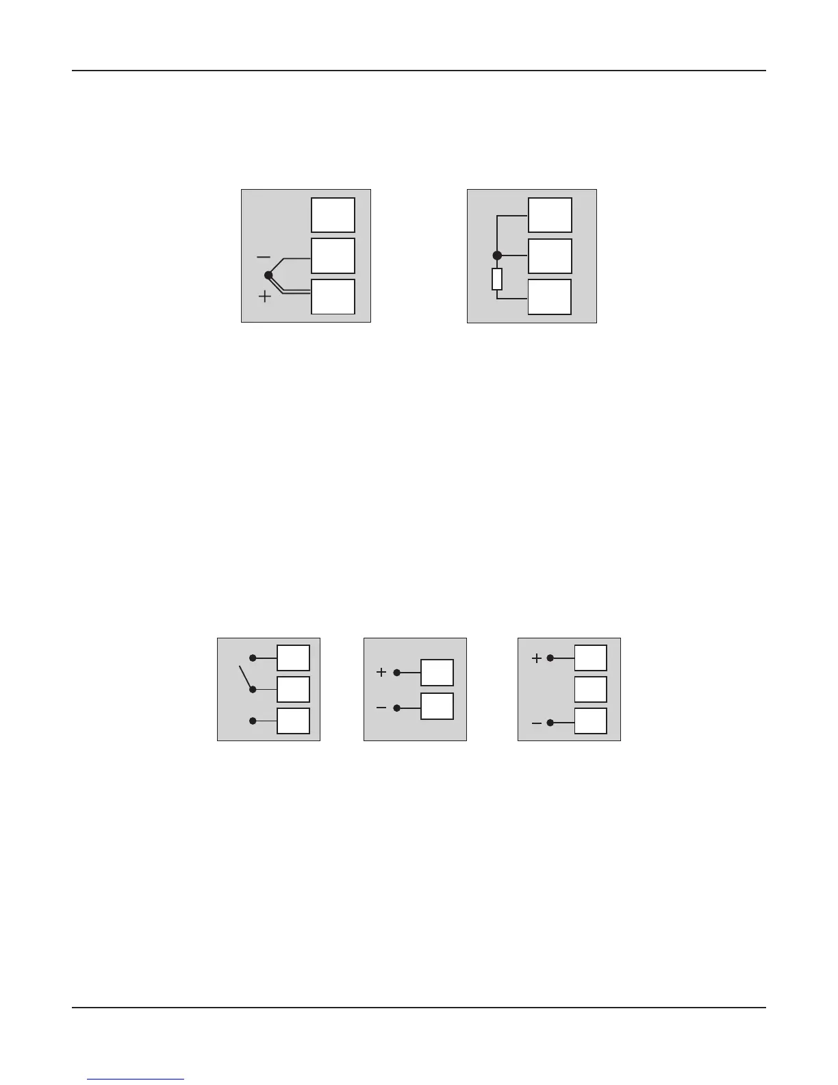
NO
C
NC
Relay Output
SSR Output mA/V Output
Relay Output
Potential-free Relay changeover contacts NO (Normally Open) and C (Common) rated 10A/240 VAC (resistive load).
SSR Output
Connect (+) and (-) terminals of SSR to terminals 11 & 10, respectively. Use Zero-Crossover, 3 to 30 VDC operated SSR.
mA / V Output
The Positive (+) of mA / V is available at Terminal 6 & the Negative (-) at Terminal 4.
OUTPUT- 2 (Alarm / Blower / Auxiliary Control)
OUTPUT- 3 (Alarm / Auxiliary Control)
The numbers in brackets indicates the terminal numbers for Output-3.
User Manual
TEMPERATURE SENSOR INPUT
Connect Thermocouple or 3-wire RTD Pt100 sensor as shown below.
3
2
1
Figure 3.2 (a)
Thermocouple
3
2
1
Figure 3.2 (b)
RTD
Thermocouple
Connect Thermocouple Positive (+) to terminal 1 and Negative (-) to terminal 2 as shown in Figure 3.2 (a). Use correct type of
extension lead wires or compensating cable. Avoid joints in the cable.
RTD Pt100, 3-wire
Connect single leaded end of RTD bulb to terminal 1 and the double leaded ends to terminal 2 and 3 (interchangeable) as
shown in Figure 3.2 (b). Use low resistance copper conductor leads of the same gauge and length. Avoid joints in the cable.
zenex96