Do you have a question about the PPI Zenex and is the answer not in the manual?
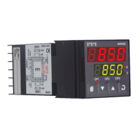
Describes the Upper and Lower Readout displays, their function, and content.
Details the status and meaning of front panel LEDs like S, T, OP1, OP2, OP3.
Describes the initial display and sequence upon controller power-up.
Explains the main display mode showing PV and SP values.
Steps for adjusting the Control Setpoint (SP) value via front panel keys.
Describes the indication and user advice during tuning/optimization.
Explains the indicators S and T related to the Soak Timer status.
Describes indications for PV errors like over-range, under-range, or sensor breaks.
Step-by-step guide for viewing and modifying parameter values in Set-up Mode.
Details input type selection for sensors like Thermocouples and RTDs.
Options for selecting temperature units (°C or °F).
Setting the maximum temperature range for proper Self-Tune/Optimize operation.
Details available options for the control output type.
Explains On-Off and PID control modes and their characteristics.
Describes Direct and Reverse control logic for heating/cooling.
Setting the differential band for ON/OFF control to prevent frequent switching.
Selects the function for the Output-2 relay (None, Alarm, Auxiliary Control, Blower).
Configures Alarm-1 parameters for OP2, including Type, Setpoint, Deviation, and Window Band.
Configures Alarm-2 parameters for OP3, including Type, Setpoint, Deviation, and Window Band.
Configures settings for Auxiliary Control function on OP3, including Offset Value and Hysteresis.
Displays the computed '% Output Power' by the PID algorithm.
Sets the time interval for ON/OFF switching in time-proportionating PID control.
Defines the process value deviation range for output power variation in PID control.
Controls automatic removal of steady-state offset error in PID control.
Enables or disables the Soak Timer function and Start/Abort commands.
Selects the time units (Min:Sec, Hrs:Min, Hours) for the Soak Timer.
Sets the preset time value for the Soak Timer in selected units.
Defines the process band around SP for the timer to start counting down.
Configures how the timer pauses based on PV relative to the Hold Band.
Determines if the control output (OP1) is forced off upon timer completion.
Command to start the Tune/Optimize operation for PID control.
Command to terminate an ongoing Tune/Optimize operation.
Enables control of PV rate of change to minimize overshoot.
Adjusts the effectiveness of the Overshoot Inhibit feature.
Enables re-tuning the controller when a substantial SP change occurs.
Adds offset to PV for removing thermal gradient or sensor errors.
Averages PV to remove rapid changes, improving stability.
Describes the basic electronic assembly comprising CPU, Power-supply, and Display PCBs.
Details jumper settings for configuring Output-2 and Output-3 modules (Relay/SSR).
Shows the external dimensions of the controller unit.
Details the required panel cutout size and minimum spacing for mounting.
Provides the electrical connection diagram for the 2 Output version.
Provides the electrical connection diagram for the 3 Output version.
Provides the electrical connection diagram for the DC Linear version.
Details how to connect Thermocouple and RTD Pt100 sensors.
Explains connections for Relay/SSR drive and DC Linear mA/V outputs.
Instructions for connecting the AC power supply to the controller.
Details connections for the serial communication port (RS485).
Describes the Upper and Lower Readout displays for the 96x96 model.
Details the status and meaning of front panel LEDs for the 96x96 model.
Describes the electronic assembly for the 96x96 controller.
Provides the electrical connection diagram for the 2 Output version (96x96).
Provides the electrical connection diagram for the 3 Output version (96x96).
Provides the electrical connection diagram for the DC Linear version (96x96).
Details how to connect Thermocouple and RTD Pt100 sensors for the 96x96 model.
Explains connections for Relay/SSR and DC Linear outputs for the 96x96 model.
Instructions for connecting the AC power supply to the 96x96 controller.
Details connections for the serial communication port of the 96x96 controller.
| Brand | PPI |
|---|---|
| Model | Zenex |
| Category | Temperature Controller |
| Language | English |