43
User Manual
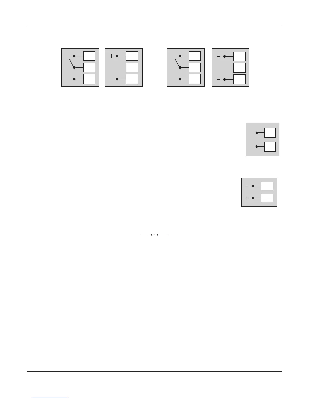
SERIAL COMMUNICATION PORT
Connect terminal 15 and 14 of the controller to the positive (+) and negative (-) terminals of the
master device.
Note that, PC as a master device cannot be connected (wired) directly to the instrument as PC is
equipped with RS232C serial port which is not directly compatible with RS485 port on instrument
side. In such cases use RS232/RS485 converter as a bridge.
Figure 3.6
15
14
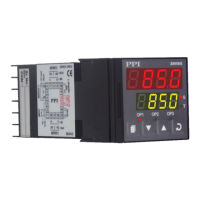
Figure 3.4 (a)
Relay Output
18
17
16
NO
C
NC
18
17
16
SSR Output
Figure 3.4 (b)
Relay Output
9
8
7
NO
C
NC
9
8
7
SSR Output
Refer Figure 3.4(a) for Output-2 & Figure 3.4(b) for Output-3 connections.
POWER SUPPLY
The controller accepts single phase, 50/60 Hz Line Voltage ranging from 85 VAC to 264 VAC. Use
well-insulated copper conductor wire of the size not smaller than 0.5mm for power supply
2
connections. Connect Line Voltage as shown in Figure 3.5.
Figure 3.5
13
12
L
N
zenex96