5114V107-UK 5
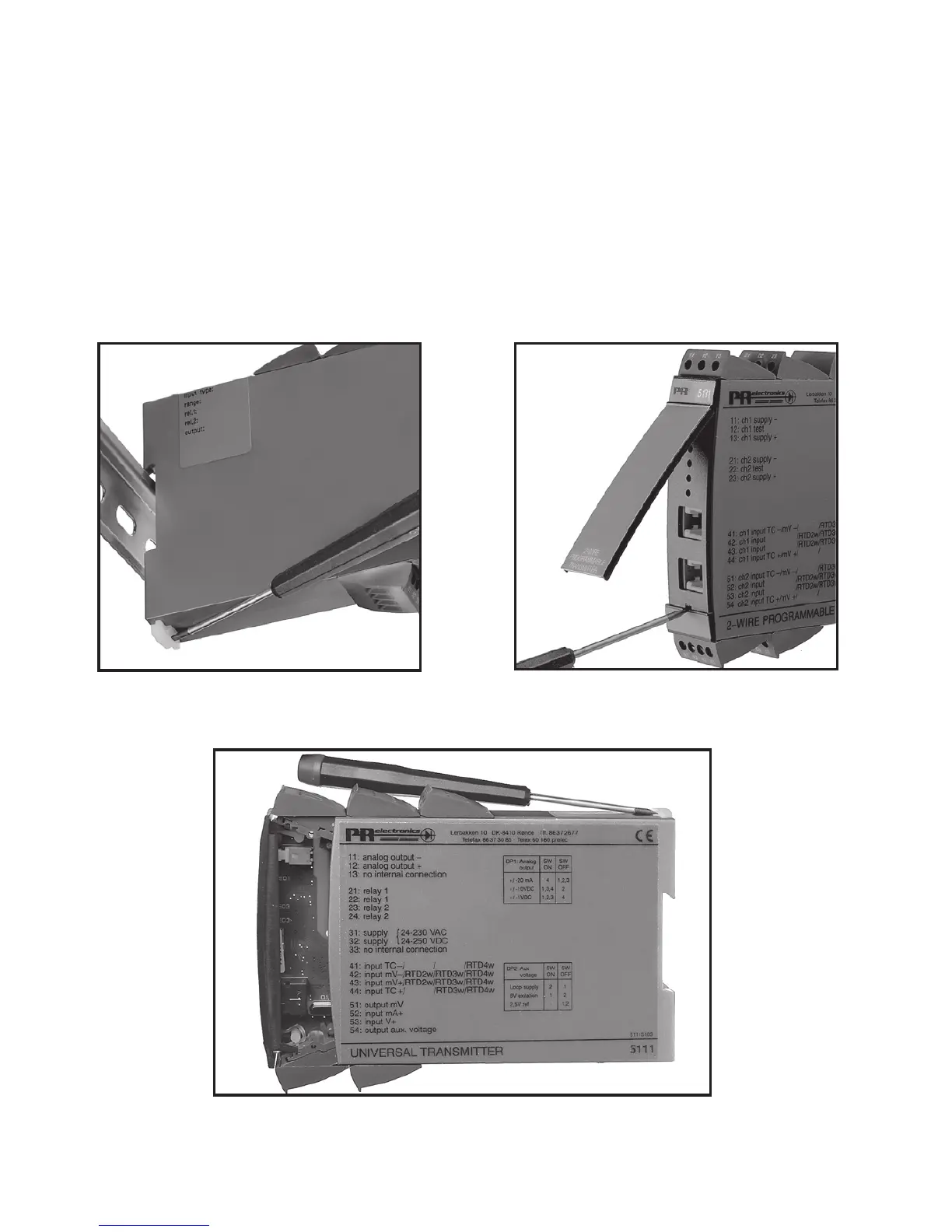
Picture 3: Access to programming
connector.
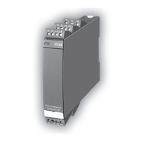
Picture 1: Separation from DIN rail.
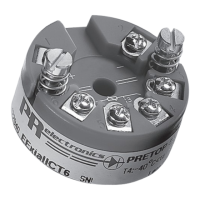
Picture 2: Removal of PCB.
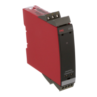
HOW TO DEMOUNT SYSTEM 5000
First, remember to demount the connectors with hazardous voltages. By lifting the
bottom lock, the device is detached from the DIN rail as shown in picture 1.
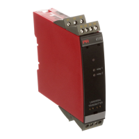
Then, by lifting the upper lock and pulling the front plate simultaneously the PCB
is removed as shown in picture 2.
Switches and jumpers can now be adjusted. By opening the front, the programming
connector is accessible as shown in picture 3.