EasyManua.ls Logo

PR PReasy 4116 User Manual

PR PReasy 4116
67 pages
Go to English
To Next Page IconTo Next Page
Page #1 background imageLoading...
Page #1 background image
Programmable displays with a wide se-
lection of inputs and outputs for display of temperature,
volume and weight, etc. Feature linearisation, scaling,
and difference measurement functions for programming
via PReset software.
Interfaces for analogue and digital
signals as well as HART
®
signals between sensors / I/P
converters / frequency signals and control systems in Ex
zone 0, 1 & 2 and for some modules in zone 20, 21 & 22.
Galvanic isolators for analogue and digital
signals as well as HART
®
signals. A wide product range
with both loop-powered and universal isolators featuring
linearisation, inversion, and scaling of output signals.
PC or front programmable modules with
universal options for input, output and supply. This range
offers a number of advanced features such as process
calibration, linearisation and auto-diagnosis.
A wide selection of transmitters for DIN
form B mounting and DIN rail modules with analogue
and digital bus communication ranging from application-
specific to universal transmitters.
Displays
Temperature
Isolation
Ex interfaces
Universal
DK
UK
FR
DE
Side 1
Page 33
Page 65
Seite 97
4 1 1 6
U n i v e r s a l
T r a n s m i t t e r
N o . 4 1 1 6 V 1 0 3 - I N ( 0 9 4 5 )
F r o m s e r . n o . 0 9 0 3 9 0 0 0 1
S I G N A L S T H E B E S T

Table of Contents

Question and Answer IconNeed help?

Do you have a question about the PR PReasy 4116 and is the answer not in the manual?

PR PReasy 4116 Specifications

General IconGeneral
BrandPR
ModelPReasy 4116
CategoryTransmitter
LanguageEnglish

Summary

Product Categories

Displays

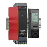
Programmable displays with various inputs and outputs for temperature, volume, and weight.

Ex Interfaces

Interfaces for analogue and digital signals, including HART, in Ex zones.

Isolation Modules

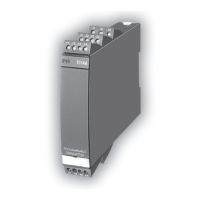
Galvanic isolators for analogue and digital signals, with loop-powered and universal options.

Temperature Transmitters

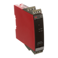
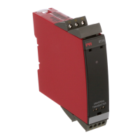
Transmitters for DIN form B mounting and DIN rail modules with communication.

Universal Transmitter

PC or front programmable modules with universal options for input, output, and supply.

Safety Warnings and Instructions

General Safety Warnings

Covers general, hazardous voltage, installation, and front plate safety.

General Safety Guidelines

General safety guidelines, definitions, environment, and mounting.

UL Installation Requirements

Calibration and Adjustment Procedures

Procedures for calibration and adjustment using safe tools.

System 4000 Dismantling and Error Handling

How to Dismantle System 4000

Step-by-step instructions for dismantling the system 4000.

LED and Display Error Indications

Explanation of error mode and LED indications for malfunction.

Order Codes and Electrical Specifications

Electrical Specifications

Details on operating range, common specs, and accuracy.

4501 Display for Error and Range Visualization

Out-of-Range Signal Display

Sensor Error Detection Limits

Error Indications and Causes

Hardware Error Codes

Hardware error readouts and their causes.

Input Signal and Configuration Errors

Errors related to input signals and configuration mismatches.

Configuration and Function Key Operation

Fast Setpoint Adjustment and Relay Test

Procedures for quick setpoint changes and relay testing.

Password Protection

How to set and use password protection for configuration.

Signal and Sensor Error Information

Display Front Error Information

Detailed error display via the 4501 front unit.

LED Indicator Error Information

Status reading via LED indicators without the display.

Relay Functions

Manual Latch Function Deactivation

Advanced Functions

Display Setup and Calibration

Adjusting display settings and performing two-point calibration.

Process Simulation and Password Protection

Simulating inputs and protecting configuration with passwords.

Auto Diagnosis and Safety Features

Routing Diagram: Advanced Settings

Routing Diagram: Manual Latch Deactivation

Scrolling Help Text Descriptions

Latch Function: Setpoint Depiction

Latch Function: Window Depiction

Relay Action: Setpoint Depiction

Relay Action: Window Depiction

Related product manuals