44
45
TC input:
Cold junction compensation (CJC)
CJC via external sensor in
connector 5910 ........................................... 20...28°C ≤ ±1°C
-20...20°C / 28...70°C ≤±2°C
CJC via internal sensor ............................... ±(2.0°C + 0.4°C * Δt)
Δt = internal temperature - ambient temperature
Sensor error detection, all TC types ........... Yes
Sensor error current:
when detecting.......................................... Nom. 2 µA
else ............................................................ 0 µA
Current input:
Measurement range .................................... 0...20 mA
Programmable measurement ranges .......... 0...20 and 4...20 mA
Input resistance ........................................... Nom. 20 Ω + PTC 50 Ω
Sensor error detection:
Loop break 4...20 mA.............................. Yes
Voltage input:
Measurement range .................................... 0...12 VDC
Programmable measurement ranges .......... 0...1 / 0.2...1 / 0...5 / 1...5 /
0...10 and 2...10 VDC
Input resistance ........................................... Nom. 10 MΩ
Current output:
Signal range (span) ...................................... 0...20 mA
Programmable signal ranges ...................... 0...20 / 4...20 / 20...0 and 20...4 mA
Load (max.) .................................................. 20 mA / 800 Ω / 16 VDC
Load stability ............................................... ≤ 0.01% of span / 100 Ω
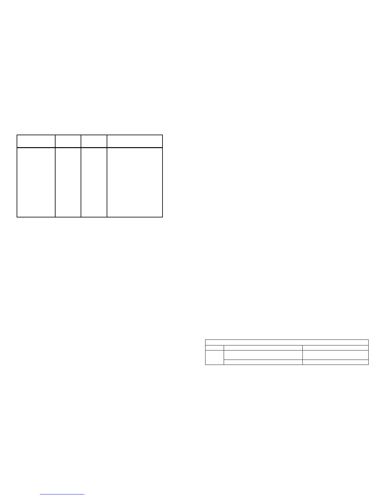
Type
Min.
value
Max.
value
Standard
B
E
J
K
L
N
R
S
T
U
W3
W5
LR
0°C
-100°C
-100°C
-180°C
-200°C
-180°C
-50°C
-50°C
-200°C
-200°C
0°C
0°C
-200°C
+1820°C
+1000°C
+1200°C
+1372°C
+900°C
+1300°C
+1760°C
+1760°C
+400°C
+600°C
+2300°C
+2300°C
+800°C
IEC 60584-1
IEC 60584-1
IEC 60584-1
IEC 60584-1
DIN 43710
IEC 60584-1
IEC 60584-1
IEC 60584-1
IEC 60584-1
DIN 43710
ASTM E988-90
ASTM E988-90
GOST 3044-84
Sensor error detection ................................ 0 / 3.5 / 23 mA / none
NAMUR NE 43 Upscale / Downscale ......... 23 mA / 3.5 mA
Output limitation:
on 4...20 and 20...4 mA signals .............. 3.8...20.5 mA
on 0...20 and 20...0 mA signals .............. 0...20.5 mA
Current limit ................................................. ≤ 28 mA
Voltage output:
Signal range ................................................ 0...10 VDC
Programmable signal ranges ...................... 0...1 / 0.2...1 / 0...10 / 0...5 /
1...5 / 2...10 / 1...0 / 1...0.2 / 5...0 /
5...1 / 10...0 og 10...2 V
Load (min.) ................................................... 500 kΩ
Relay outputs:
Relay functions ............................................ Setpoint, Window, Sensor error, Latch
Power and Off
Hysteresis, in % / display counts ............... 0,1...25% / 1...2999
On and Off delay ......................................... 0...3600 s
Sensor error detection ................................ Break / Make / Hold
Max. voltage ................................................ 250 VRMS
Max. current ................................................ 2 A / AC or 1 A / DC
Max. AC power ........................................... 500 VA
Ex / I.S. approval:
FM, applicable in ......................................... Class I, Div. 2, Group A, B, C, D
Class I, Div. 2, Group IIC
Zone 2
Max. ambient temperature for T5 ............... 60°C
Marine approval:
Det Norske Veritas, Ships & Offshore ......... Standard for Certification No. 2.4
GOST R approval:
VNIIM, Cert. no. ........................................... See www.prelectronics.com
Observed authority requirements: Standard:
EMC 2004/108/EC ...................................... EN 61326-1
LVD 2006/95/EC .......................................... EN 61010-1
FM ............................................................... 3600, 3611, 3810 and ISA 82.02.01
UL, Standard for Safety .............................. UL 508
of span = of the currently selected measurement range
Visualisation in the 4501 of sensor error detection and
input signal outside range
Sensor error check:
Device: Configuration Sensor error detection:
4116
R1, ERR.ACT=NONE - R2, ERR.ACT=NONE,
OUT.ERR=NONE.
OFF
Else: ON