10
BI-DIRECTIONAL TOOL TURRET
Following points should be noted while selecting control system for turret :
1. Direction of rotation of motor for shortest indexing time is to be decided by control system.
2. Indexing times of these turrets are short. It is necessary to select particularly fast PLC
(programmable logic controller) for the control of turret operations.
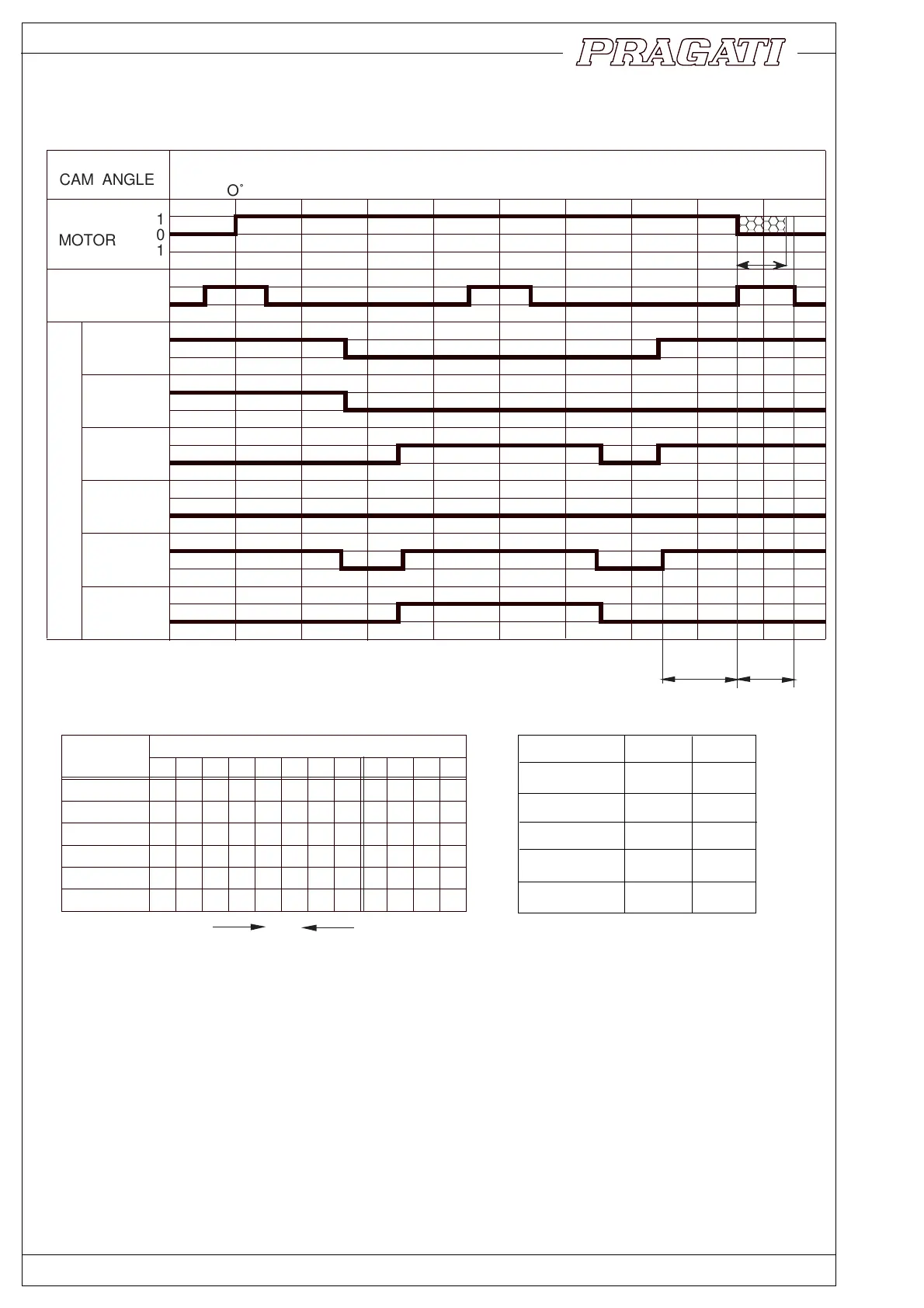
3. Referring to the signal diagram, value of T3 is particularly critical. Motor must come to a physical
halt within this time. Otherwise, the turret will get de-clamped and the proximity switch signal will be
lost. Following measures are suggested for stopping the motor in minimum possible time.
a. Control should be capable of detecting the proximity switch signal within 3 to 6 ms.
b. Solid state relays should be incorporated in the motor circuit to ensure fastest possible dis-
connection. Regular contactors can be used for motor direction selection, followed by solid state
relays, at least in two phases.
7. Electrical Signals
123456789101112
101010101010
011001100110
000111100001
000000011111
111111111111
110100110010
POSITION NUMBER
BIT 1
BIT 2
BIT 3
BIT 4
STROBE
PARITY
T1 T2 T3
ms m s ms
max
FAST
STD
FAST
STD
STD
BTP-100
BTP-80
BTP-63
110 60 50
135 75 60
100 55 45
110 60 50
80 45 35
TABLE 1 ENCODER SIGNALS
TABLE 2
CCW
CW
TURRET
CLAMP
SWITCH
1
0
1
0
1
0
1
0
1
0
1
0
1
0
ENCODER
BIT 1
BIT 2
BIT 3
BIT 4
STROBE
PARITY
T
1
T2
a
a
CAM ANGLE
MOTOR
1
0
1
O˚ 180˚
360˚
360˚
180˚
POSITION 4
POSITION 5
TURRET CLAMP
POSITION 3
START
T3
T1 ms T2 ms
BTP-125 175 135
BTP-100 150 115
BTP-80 125 95
BTP-63 100 75
BTP-50 75 60
 Loading...