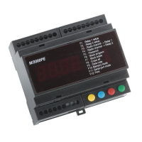
M/2000E
18 17 16 15 14 13 12 11 10 9 8 7 6 5 4 3 2 1
19 20 21 22 23 24
FUN DEC INC VAL
YELLOW BLUE RED GREEN
F1 : Relay 1 setup
F2 : Relay 2 setup
F3 : Radio channel - Relay 1
F4 : Radio channel - Relay 2
F5 : Password
F6 : Block program
F7 : Block erase
F8 : Erase all
F9 : Data copy
F10 : Memory mode
F11 : Serial port mode
F12 : Print
M/2000PE
Black & Shield
Green
White
Red
Black & Shield
White
Green
Red
Normally Open
Common
Normally Closed
Normally Open
Common
Normally Closed
12-24v Power Input
Ground
Antenna Core
Note:
Make sure that terminal 4 is connected to 6 and termnial 13 is connected to 15 (see figure) in order to enable the corresponding relay
outputs 1 & 2. This contact is particularly useful for enabling, for instance, the relay outputs of the M2000PE via external devices such as buried
magnetic coils (opening command given by the M2000PE only in case of a vehicle being present on the coil so as to avoid undesired opening caused
by accidental radio transmission) or via timed relays (M2000PE enabled within a given time interval), as well as for closing the normally open contact
of a switch, and so on.
1 Port 2 – Relay Normally Closed
2 Port 2 – Relay Common
3 Port 2 – Relay Normally Open
4 Port 2 – Relay Enabling Contact
5 Port 2 – Relay Activation (when linked to ground)
6 Ground
7 Port 2 – Data Input (DATA 1)
8 Port 2 – Data Input (DATA 0)
9 Port 2 – Output for reader power supply (9vdc)
10 Port 1 – Relay Normally Closed
11 Port 1 – Relay Common
12 Port 1 – Relay Normally Open
13 Port 1 – Relay Enabling Contact
14 Port 1 – Relay Activation (when linked to ground)
15 Ground
16 Port 1 – Data Input (DATA 1)
17 Port 1 – Data Input (DATA 0)
18 Port 1 – Output for reader power supply (9vdc)
19 Antenna Core
20 Antenna Braid
21 Serial Line (RS485)
22 Serial Line (RS485)
23 Power Supply + 12/24V ac/dc
24 Power Supply – 12/24V ac/dc