Do you have a question about the Precisa 300 Series and is the answer not in the manual?
Provides an elementary block diagram of the weighing system's components and connections.
German for "Circuit Diagram" or "Schematic Diagram".
Details the multifunction box board, a key component of the system.
Explains the data output interface using a 20mA current loop.
Covers the mechanical aspects of the balance, excluding the weighing cell itself.
Details the component that holds the weighing pan.
Focuses on the weighing cell, a critical part of the balance's operation.
Describes the sensor mechanism and its specific model number.
Details the low-resolution main electronic board.
Details the high-resolution main electronic board.
Information about the analogue board and its function.
Lists tools required for service and calibration procedures.
Step-by-step guide for assembling the weighing cell.
Instructions for adjusting the balance's settings and calibration.
A schematic showing the interconnected components of the weighing system.
A numbered list of all components referenced in the elementary diagram.
Explains the mechanical principles of the balance's operation.
Explains how weight is measured and regulated via feedback loops.
Describes how electrical signals from the measurement are processed.
Lists and describes the parts of the microprocessor system, including memory types.
Outlines the various functions performed by the microprocessor.
Identifies components of the balance assembly through a numbered diagram.
Lists part numbers for housing and weighing pan components.
Lists part numbers for electronic boards and transformers.
Lists part numbers for measure resistors and interface cables.
Lists part numbers for various screws, washers, and spring washers.
Details the top and bottom parts of the pan holder assembly.
Lists components like springs, centring bushes, and screws for the pan holder.
Lists part numbers for the holder and associated washers.
Lists part numbers for springs and support bolts used in the pan holder.
Details the shaft and support bolt used in the pan holder assembly.
Shows numbered components of the weighing cell from a top perspective.
Lists part numbers for chassis, balance arm, and various flexure parts.
Lists part numbers for the sensor mechanism, vane, and related parts.
Lists part numbers for flexure straps, bolts, screws, and nuts.
Lists part numbers for support angles and specialized screws.
Schematic illustration of the sensor mechanism with numbered parts.
Lists the parts and their corresponding key numbers for the sensor mechanism.
Shows the assembly of the windshield with numbered parts.
Lists part numbers for sliding rails, covers, and related components.
Lists part numbers for connecting pieces, under plates, and front panes.
Shows the placement of components on the low-resolution main board.
Table detailing differences in components and measuring resistors across main board types.
Explains the correspondence between main board and EPROM labels.
Details the function of various jumpers on the main board.
Shows the interconnections between controllers and data interfaces.
Details the interface between the microcontroller and memory components.
Illustrates signal processing circuits involving op-amps and logic gates.
Shows logic for display control and input handling.
Details timing circuits and counter logic on the main board.
Lists part numbers for test points and ICs U1-U12.
Lists part numbers for resistors R1-R15 and capacitors.
Lists part numbers for diodes and transistors on the main board.
Lists part numbers for ICs and connectors on the main board.
Shows the placement of capacitors and voltage regulators on the power supply board.
Details the transformer connections and the output voltages provided.
Shows the circuit diagram for rectifiers and voltage regulators.
Lists part numbers for capacitors and voltage regulators.
A diagram showing the placement of components on the high-resolution main board.
Details component variations and service numbers for different main board types.
Explains EPROM labeling conventions and jumper configurations.
Illustrates the connections between controllers and data interfaces.
Shows the microcontroller's interface with peripherals and memory.
Details analog signal processing circuits using op-amps.
Illustrates logic circuits for display control and input handling.
Lists part numbers for test points and ICs U1-U12.
Lists part numbers for resistors R1-R15 and capacitors.
Lists part numbers for resistors R8-R42 and capacitors.
Lists part numbers for diodes and ICs D1-D25.
Shows the placement of capacitors and voltage regulators on the high-resolution power supply board.
Details the transformer connections and the output voltages provided.
Shows the circuit diagram for rectifiers and voltage regulators.
Lists part numbers for capacitors and voltage regulators.
Shows the arrangement of components on the analogue board.
Details the circuit diagram, focusing on op-amps and signal paths.
Lists part numbers for transistors, diodes, and integrated circuits.
Lists part numbers for resistors and capacitors on the analogue board.
Shows the arrangement of components on the analogue board.
Details the circuit diagram, focusing on op-amps and signal paths.
Lists part numbers for transistors, diodes, and integrated circuits.
Lists part numbers for resistors and capacitors on the analogue board.
Lists standard screwdrivers and specialized tools for service procedures.
Explains instruction symbols and the procedure for exchanging flexure sheets.
Step-by-step guide for introducing the support piece into the balance arm.
Details assembling the balance arm with the chassis and support piece.
Instructions for assembling the pot, plunger coil, and related parts.
Describes the assembly of the sensor mechanism and flexure arm.
Covers the final assembly steps, including soldering and connecting plugs.
Shows the main board and power supply board connections.
Guides on adjusting symmetry voltage and checking initial load deviations.
Details procedures for corner load and linearisation adjustments.
Covers linearity checks for the second range and instability testing.
Describes hysteresis checking and analogue output zero adjustment.
Guides on adjusting analogue output and capacity indicator.
Lists final checks and required information for technical assistance.
Explains how to check and adjust corner load deviations.
Provides examples of adjustment and specifies the tolerance.
Lists errors related to incorrect handling and operational issues.
Details fatal errors occurring during normal operation.
Lists errors identified during servicing or diagnostic tests.
Describes errors encountered during adjustment procedures.
Lists errors related to incorrect initial load conditions.
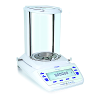
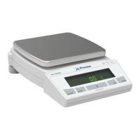
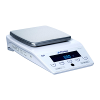
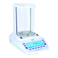
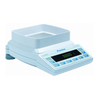
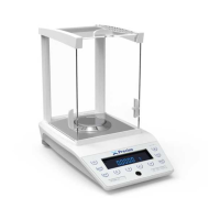
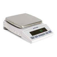
| Readability | 0.001 g - 0.1 g |
|---|---|
| Pan Size | Ø 80 mm - 180x160 mm |
| Calibration | Automatic, external |
| Display | LCD |
| Repeatability | 0.001 g - 0.1 g |
| Linearity | 0.002 g - 0.2 g |
| Interface | RS232 |
| Housing | plastic |
| Operating Temperature | 40 °C |
| Units | g, kg, oz, lb, ct |

 Loading...