Do you have a question about the Precision Aerobatics Addiction X V2 and is the answer not in the manual?
Mounting and adjusting the aerodynamic wheel pants.
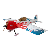
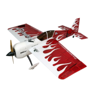
The Precision Aerobatics Addiction X V2 is a high-performance radio-controlled (RC) model aircraft designed for extreme aerobatics and 3D maneuvers. Its construction emphasizes lightweight design and strength, achieved through unique engineering and untraditional production techniques, including the revolutionary PA FiberFusion® technology and extensive use of carbon fiber. This results in an aircraft with an incredibly low wing loading, contributing to its outstanding flying characteristics.
The Addiction X V2 is designed to be assembled by the user, with a comprehensive manual guiding the process. Pre-assembly involves inspecting all kit components for damage or warp, particularly the ailerons, elevator, and rudder, and correcting any warps using a modeling iron. Care must be taken to avoid excessive heat, which can damage the covering film. All sharp edges of the covering trims should be sealed down, especially on wing and elevator tips, to prevent peeling. Small bubbles or wrinkles in the covering film can also be removed with a hobby iron, again with extreme caution to avoid warping.
Assembly begins with making openings in the covering film for various components like aileron servo cables, wing bolts, elevator servo, landing gear, cooling air exit, stabilizer slot, and aileron servo bays. These openings are best made by ironing around the edges first to prevent peeling, then cutting with a heated paperclip or sharp modeling knife. Identifying aileron servo bays under opaque covering can be aided by plugging in LED lights.
Aileron installation involves gluing eight large hinges into the ailerons first, then test fitting them into the wing. The aileron deflection is set to approximately 50 degrees up and down to create an even hinge gap, then thin CA glue is applied to secure the hinges. A crucial step is sealing the aileron hinge gap with a supplied covering strip, creased into a "V" and ironed down along the hinge line and aileron while deflected. This ensures a completely sealed gap, vital for flight characteristics and preventing flutter.
Aileron servo installation requires feeding the servo cable through the wing openings and inserting the servos with the output shaft closer to the aileron. Mounting holes are drilled, and screws are installed, with a drop of thin CA applied to set the threads. Hard mounting of servos, without rubber grommets and eyelets, is recommended to avoid excessive flex and loss of control resolution.
Aileron control linkages are prepared using CF pushrods and control horns. The CF control horns are sanded at the base for better gluing, then test fitted into the aileron slot. Metal clevises are installed onto the control horns, with the mounting hole slightly enlarged for a precise, slop-free fit. The clevis bolt is screwed in, and movement is tested for smoothness. Permanent Loctite is applied to secure the bolt. The CF horn is then epoxied into the aileron slot, ensuring it is 90 degrees perpendicular to the control surface. Plastic servo arms are temporarily installed and cut to achieve a 90-degree angle to the servo case when centered. Carbon fiber servo arms are recommended for maximum control throws. The CF pushrods are notched and roughened at the ends, then epoxied into the clevis and ball link, ensuring the servo arm is in the neutral position.
LED night flying is powered by the main flight battery, with a PA light harness used to switch on the lights. Epoxy is applied to the LED cable soldering joints as a precaution against breakage.
Elevator and horizontal stabilizer installation involves gluing four wide hinges into the elevator first, then fitting the elevator into the stabilizer. Deflection is set to 50-55 degrees, and thin CA is applied to secure the hinges. The elevator hinge gap is sealed with a creased covering strip, similar to the ailerons, to prevent flutter. The stabilizer is inserted into the fuselage slot from the rear, requiring balsa removal. The stabilizer is aligned parallel to the wing tube and 90 degrees to the fin, then epoxied in place. A balsa wedge is then glued into the rear fuselage gap.
Rudder and tail landing gear installation involves preparing the tail landing gear by removing covering, drilling a hole for the wire, and creating indentations on the wire for better glue bonding. The LG is then epoxied into the slot. For the rudder, hinges are glued into the rudder first with thin CA, then the rudder is test fitted into the fuselage. The rudder hinge gap is sealed with supplied strips, and any warp in the rudder is corrected with an iron.
Elevator servo installation requires preparing a servo lead extension by soldering and insulating cables. The elevator servo is installed with the output shaft closer to the control surface. Mounting holes are drilled, and screws are installed. The elevator control horn is epoxied into its slot, ensuring it is 90 degrees perpendicular. Metal clevis, plastic ball link, and CF pushrod are installed, with the elevator ball link in the outer mounting hole of the arm.
The motor box, a separate part, is designed to be replaceable after a crash. Prior to installation, all pre-glued joints are reinforced with wood glue or epoxy. Composite plates are epoxied to the motor box front perimeter, and epoxy is applied to mounting plate vent holes. The motor box is secured to the fuselage bulkhead with five carbon pins, then epoxied along the entire seam.
Motor and ESC installation involves installing the Thrust 45 Revo motor onto the firewall using supplied hardware, ensuring the X mount sits flush. Temporary Loctite is applied to all mounting bolts. The Quantum 45 HV Pro ESC is mounted as far forward as possible on one side of the motor box using foamed double-sided sticky tape and zip ties. The ESC battery wires are trimmed and routed, and motor cables are connected. Motor rotation direction is verified. Air baffles are assembled and glued to the motor box to improve airflow.
Landing gear installation involves attaching wheels to the CF landing gear struts using bolts and lock nuts, ensuring free wheel rotation. Wheel pants are positioned over the wheels, marked, drilled, and attached with self-tapping screws. The LG struts are then installed onto the fuselage using bolts and washers. The covering around the landing gear bay is trimmed and ironed down.
Cowling attachment involves notching the cowling to clear the landing gear, marking drill locations, and partially peeling off masking tape. The cowling is aligned with the spinner backplate and motor shaft, then drilled and secured with self-tapping screws.
Propeller and spinner installation involves mounting the propeller and a lightweight carbon fiber spinner, ensuring proper clearance and balance. Temporary Loctite is recommended for mounting bolts.
Wing attachment involves sliding the CF wing tube into one wing panel, then fitting the wing to the fuselage, aligning anti-rotation pins. The wing is secured with a nylon wing bolt. The process is repeated for the other wing panel. Any gaps at the wing root are addressed by sanding the wing tube.
Center of Gravity (CG) is set to 135mm aft from the leading edge at the wing root, with fine adjustments made by sliding batteries. A CG machine is recommended for accuracy.
Transmitter setup involves removing servo arms and propeller, powering up the radio system, resetting servos to neutral, and reinstalling servo arms. Control surface directions are verified, and sub-trims are adjusted for neutral positions. Servo travel is adjusted to prevent binding.
Maiden flight should be on a calm day. Bench tests are performed to verify prop adapter, gear, and propeller balance. Flight trimming involves adjusting TX trims after takeoff. Initial flight timer settings are conservative, then gradually adjusted based on battery consumption.
Decals are applied as a final touch. Small wrinkles in covering trim are secured with clear tape.
Optional Carbon Fiber Vortex Generators (VGs) can be installed by locating pre-cut slots using LED lights, roughening gluing tabs, dry fitting, and then epoxying them into the slots, ensuring they are perpendicular to the wing surface.
| Power System | Electric |
|---|---|
| Recommended Battery | 3S 2200mAh LiPo |
| Wingspan | 48.0 in (1220 mm) |
| Radio | 4-channel or more |
| Servos | 4 x High Voltage Micro Servos (10-12g) |