4
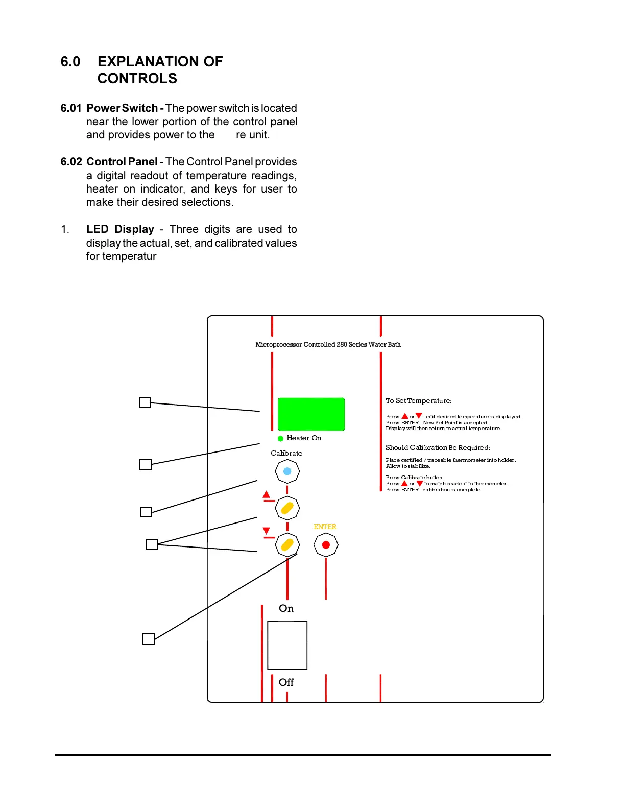
3ODFHFHUWLILHGWUDFHDEOHWKHUPRPHWHULQWRKROGHU
3UHVV(17(5FDOLEUDWLRQLVFRPSOHWH
3UHVVRUWRPDWFKUHDGRXWWRWKHUPRPHWHU
2II
2Q
(17(5
3UHVV&DOLEUDWHEXWWRQ
$OORZWRVWDELOL]H
q
p
6KRXOG&DOLEUDWLRQ%H5HTXLUHG
'LVSOD\ZLOOWKHQUHWXUQWRDFWXDOWHPSHUDWXUH
3UHVV(17(51HZ6HW3RLQWLVDFFHSWHG
3UHVVRUXQWLOGHVLUHGWHPSHUDWXUHLVGLVSOD\HG
&DOLEUDWH
+HDWHU2Q
p
q
7R6HW7HPSHUDWXUH
6.0 EXPLANATION OF
CONTROLS
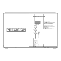
6.01 Power Switch - The power switch is located
near the lower portion of the control panel
and provides power to the entire unit.
6.02 Control Panel - The Control Panel provides
a digital readout of temperature readings,
heater on indicator, and keys for user to
make their desired selections.
1. LED Display - Three digits are used to
display the actual, set, and calibrated values
for temperature.
2. Heater On Lamp - The "HEATER ON" lamp
is lit when power is applied to the heater.
3. Calibrate Key - This key puts the unit in
calibrate mode to match a traceable
thermometer to the actual temperature
display.
4. Temperature Selection Keys - These keys
are used to increase or decrease the setpoint
and/or calibrate temperature selections.
5. Enter Key - The enter key is used to store a
new setpoint or calibration value.
1
2
3
4
5