This document is an installation and service manual for Precision General Purpose Water Baths, covering Models 180, 181, 182, 183, 184, 185, 186, and 188.
Function Description
Precision General Purpose Water Baths are designed for a wide variety of serological research procedures and other general laboratory applications. These units provide a controlled heated water environment for samples. All models, except Model 180, feature an adjustable support shelf with three height levels. Model 180 is equipped with a non-adjustable diffuser shelf.
Important Technical Specifications
The water baths feature a one-piece, deep-drawn stainless steel chamber with a welded and painted galvanized steel outer body. Depending on the model, they are equipped with either one or two heaters attached to the bottom of the bath chamber. Most models include a stainless steel cover (Model 181 has a plastic cover) to facilitate faster temperature recovery and reduced power consumption, enabling the baths to reach and maintain 100°C.
Electrical Characteristics and Capacity:
The manual provides a detailed table outlining the electrical characteristics (Volts, Watts, Amps) and capacity (Liters, Gallons) for each model:
- Model 180:
- Catalog Numbers: 51221070 (120V), 51221071 (230V)
- Watts: 225
- Amps: 1.9 (120V), 1.0 (230V)
- Capacity: 1.5 Liters, 0.4 Gallons
- Model 181:
- Catalog Numbers: 51221064 (120V), 51221211 (230V)
- Watts: 225
- Amps: 1.9 (120V), 1.0 (230V)
- Capacity: 2.5 Liters, 0.7 Gallons
- Model 182:
- Catalog Numbers: 51221073 (120V), 51221068 (230V)
- Watts: 300
- Amps: 2.5 (120V), 1.3 (230V)
- Capacity: 5.5 Liters, 1.5 Gallons
- Model 183:
- Catalog Numbers: 51221060 (120V), 51221062 (230V)
- Watts: 400
- Amps: 3.3 (120V), 1.7 (230V)
- Capacity: 12.0 Liters, 3.2 Gallons
- Model 184:
- Catalog Numbers: 51221075 (120V), 51221069 (230V)
- Watts: 600
- Amps: 5.0 (120V), 2.6 (230V)
- Capacity: 19.5 Liters, 5.2 Gallons
- Model 185:
- Catalog Numbers: 51221065 (120V), 51221066 (230V)
- Watts: 600
- Amps: 5.0 (120V), 2.6 (230V)
- Capacity: 18.0 Liters, 4.9 Gallons
- Model 186:
- Catalog Numbers: 51221072 (120V), 51221074 (230V)
- Watts: 1200
- Amps: 10.0 (120V), 5.2 (230V)
- Capacity: 43.0 Liters, 11.4 Gallons
- Model 188 (Dual Pans):
- Catalog Numbers: 51221061 (120V), 51221063 (230V)
- Watts: 800
- Amps: 6.7 (120V), 3.5 (230V)
- Capacity: 12.0 Liters (Both Pans), 3.2 Gallons (Both Pans)
Volume calculations are based on a water level approximately 1" (25mm) from the chamber top.
Usage Features
Installation:
- Location: The bath should be placed away from drafts, ventilation outlets, radiators, and other rapidly changing ambient conditions for uniform operation. A minimum of 4" clearance is required around the rear, top, and sides, and 8" between units if placed side-by-side, to ensure proper ventilation.
- Electrical Connections: The apparatus must be properly grounded using its three-prong (grounding) plug. Users are warned against cutting or removing the third prong or using a two-prong adapter. The power supply voltage must match the nameplate specification. It is critical to ensure the total current demand on the circuit does not exceed the fuse or circuit breaker rating.
Operation:
- Shelf Placement: The stainless steel diffuser shelf (corners facing downward) should be placed inside the bath chamber to provide a sample base and protect samples from the hot bath bottom. For models 181 and above, a Leg Extension Kit is included to increase shelf height if needed.
- Filling Bath: Distilled water is recommended to prevent corrosion and reduce cleaning needs. 18 MEG deionized water should be mixed 50% with regular tap water if it's the only source. The bath should be filled, allowing for sample displacement and thermal expansion. Maximum liquid levels are 1-1/2" from the top surface for Model 181 and above, and 3/4" for Model 180.
- Bath Cover: The supplied cover should be used to conserve energy and reduce evaporation, and is necessary to reach and maintain 100°C. Aluminum foil should not be used as a cover due to potential electrolytic corrosion. Care must be taken when removing the cover to prevent condensation from falling onto the bath surface.
- Bath Thermometer: Each bath comes with a thermometer and O-ring. The O-ring is slipped onto the thermometer, which is then inserted through a metal clip until the immersion depth indicator is at or below the water surface. The thermometer bulb must always be above the diffuser shelf.
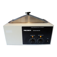
- Power ON: The power switch is turned to "ON" to energize the heater and illuminate the amber pilot lamp.
- Setting Thermostats:
- The dial numbers on the front panel are for reference only, not actual water temperatures.
- Both Temperature Control and High Temperature Limit thermostat knobs are initially turned fully clockwise. The Temperature Control Pilot lamp should illuminate.
- Once the desired bath temperature is reached, the High Temperature Limit Thermostat is slowly turned counterclockwise until its pilot lamp illuminates, then turned clockwise to the next highest reference number until the light goes off. This sets the high temperature limit approximately 5° above the desired bath temperature.
- The Temperature Control Thermostat is then turned counterclockwise until both pilot lamps are off, and then clockwise until the Temperature Control pilot lamp just lights. The unit is allowed to stabilize, and the thermostat is readjusted as necessary.
- Safety: Users are warned to wear safety glasses. Exercise care when using acidic or caustic solutions, as they can attack the galvanized steel bath body. Spills must be immediately drained, and the unit thoroughly flushed and cleaned. The bath should not be left unattended during the setting procedure.
Maintenance Features
General Maintenance:
- Cleaning: Spills, especially of corrosive chemicals, should be removed immediately. The stainless steel surface should be cleaned with mild soapy water and rinsed with copious amounts of clean water. Soap-filled or metallic pads should not be used. For stubborn stains, a plastic light-duty cleansing pad can be used, rubbing gently in the direction of the metal grain.
- pH Control: Distilled water is recommended. Maintain pH between 7 and 9 to minimize corrosion. If de-ionized or reverse-osmosis water is used, 20-40 ppm (20-40 mg/liter) disodium phosphate or sodium bicarbonate should be added to achieve a pH of 7 to 9. Regular tap water with total solids <500 ppm may be used if other options are unavailable. Regularly check pH; adjust with disodium phosphate (to increase pH <6.0) or sodium bisulfate (to decrease pH >10.0). Avoid harsh alkalines or acids.
- Anti-Fungal/Anti-Bacterial Additives: These are permissible if the aqueous solution's pH remains between 7 and 9 and they are not harmful to stainless steel.
- Prevention of Scale Buildup: Additives for swimming pools/spas may be acceptable in circulating baths but are generally not effective in static baths. Using distilled, deionized, or RO water (treated as described) is best. If scale buildup is detected, clean the bath and replace water.
- Other Water Additives: Regular cleaning with mild soapy water and distilled water rinse is recommended. If certain chemicals (listed in the manual, e.g., Aluminum Chloride, Ferric Chloride, Sulfuric Acid) must be used, limit exposure to a maximum of four hours and clean surfaces immediately afterward with distilled water.
Chamber Disinfecting:
Materials known to be effective include household bleach, glutaraldehyde, and alcohol. Users should consult their staff chemist for advice on specific chemicals. Always rinse with copious amounts of clean water, air dry, and/or refill with fresh water, following the "WATER" guidelines.
Service (Heater Element and Thermostat Replacement):
- Safety: The unit must be disconnected from the power source before servicing. All service should be performed by qualified service personnel.
- Heater Element Replacement:
- Turn power switch "OFF" and disconnect power.
- Turn bath upside down, remove bottom plate and fiberglass insulation.
- Disconnect leads from heater element.
- Remove hex nuts fastening the heater element and remove the element.
- Transfer FiberFax insulation from the old element to the new one.
- Fasten the new heater element and connect leads, ensuring wires do not touch the element.
- Replace insulation and bottom plate. No thermal compounds or paste should be used on the heater.
- Thermostat Replacement (Sensing Bulb WITHIN Bathpan):
- Turn switch "OFF" and disconnect power.
- Remove shelf and drain bath.
- Remove thermostat control knob.
- Place bath on its side, remove bottom plate and insulation to access thermostat fitting.
- Remove screws fastening thermostat to control panel.
- Remove wires from thermostat terminals, marking their locations.
- Hold the fitting under the bath stationary, unscrew locknut inside bath chamber, and remove from capillary.
- Feed thermostat capillary out through the hole in the bottom of the chamber.
- Replace O-ring on the bottom side of the chamber with a new Viton O-ring.
- Complete installation by reversing the procedure, ensuring all wiring is away from the heater and insulation is replaced to prevent wire shorting. Care must be exercised not to crimp or twist the capillary or over-tighten the locknut, which could cause leaks.
- Thermostat Replacement (Sensing Bulb UNDER the Pan):
- Put power in "OFF" position and disconnect power.
- Turn bath upside down and remove bottom plate and fiberglass insulation.
- Mark the location of the wire leads on the thermostat and disconnect.
- Remove thermostat control knob.
- Remove two screws fastening thermostat to control panel.
- Loosen the two hex nuts holding the thermostat bulb bracket and pull the thermostat and bulb out from behind the control panel.
- Mount the new thermostat by reversing steps A through G. Ensure wires do not touch the heater element.
Warranty:
Precision warrants its products against defects in material and workmanship for a period of no less than one (1) year from the date of delivery. The sole obligation is to repair or replace defective parts FOB factory or locally, provided the customer notifies Precision promptly. Labor by non-Precision employees is not covered. The warranty does not extend to consequential damage or unauthorized repairs/modifications. All defective components are replaced free of charge for one year; labor is free if the apparatus is returned to the factory prepaid.