band-width,
desirable
signal to noise
ratios
are
obtainable.
However,
along
with
this wide-band
transmission,
comes
the
consequent
necessity of
transmission
at
carrier
frequencies
which
are
considerably
higher than
those
associated
with
the
regular
broadcast
band.
Frequencies
between
40 and
44
megacycles
were
originally
temporarily
chosen
and
today
F.M. is
located
in the
range
of
88-108 Mc.
The
final
frequency
selection
involved
factors
such
as
decreased
effects
of
atmospheric
and
man-made
dis-
turbances,
as
well as
desirable
radiation
characteristics
for
local
coverage,
etc.
We
have noted
that carrier
frequency
deviation is pro-
portional to
the
INTENSITY
OF
modulation.
The frequency
of the
modulating
sound
determines
the
rate at
which the
carrier
shifts
frequency. To
elaborate,
let us
assume
the
same 90
megacycle
carrier is to be
modulated
100%
by a
100
cycle
tone.
The
transmitter
in
question
creates a
devia-
tion
of
plus and
minus
75 Kc
at
100%
modulation.
Now,
inasmuch as
a
100
cycle note
is
causing the
modulation,
the
carrier
frequency
(considering
only
one
half of the
band
width)
is
then
shifting
from 90
megacycles to 90
Mc
plus
75 Kc
and
back
again,
100
times a
second. If a
1000-cycle
note was
the
modulating
tone,
this
would
happen
1000 times
a
second.
Inasmuch as
we
are
now
involved
with
special
trans-
mission
characteristics,
a
special
receiver,
or
at least a
special
tuner is
required,
capable
of
covering
the 88
to 108
mega-
cycles
spectrum.
Furthermore,
it
must
tune with
reasonably
uniform
response
over
a
band
width
of 100 to 200
kilocycles.
In
addition,
since a
frequency
modulated
carrier is
essen-
tially
of
CONSTANT
AMPLITUDE,
means
must
be
provided in
the
receiver to
overcome
the
effects
of
fading,
sharp
noise
impulses
or
other
forms of
transient
interference
which are
in
the
category
of
amplitude
variations.
Still
further,
the
receiver
must
provide a
method for
con-
verting
the
carrier
frequency
deviations
back
into the same
audio sounds
which were
originally responsible
for their
creation.
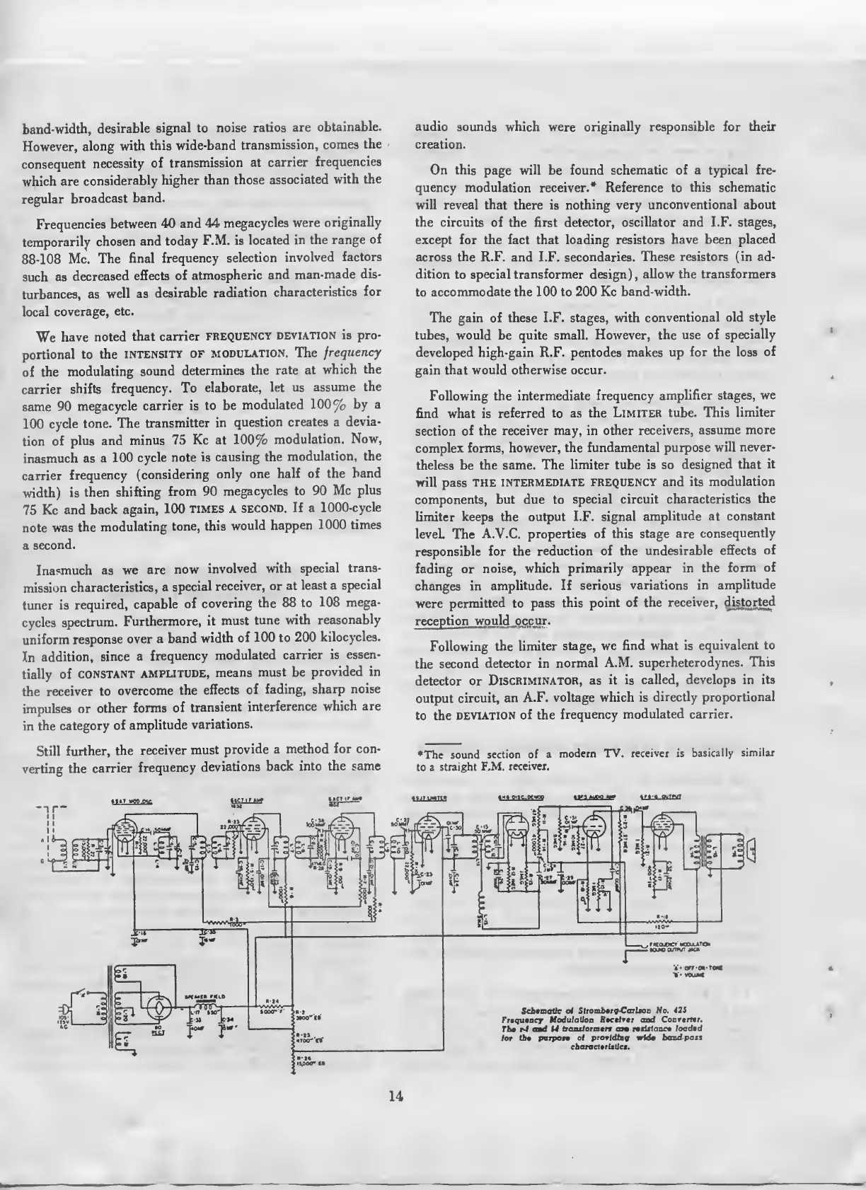
On this
page
will
be found
schematic of a typical fre-
quency modulation receiver.* Reference to
this
schematic
will
reveal
that
there is nothing very
unconventional about
the circuits
of the first
detector, oscillator and I.F.
stages,
except for the fact that loading
resistors have been
placed
across the R.F.
and I.F. secondaries. These resistors
(in ad-
dition
to
special
transformer design),
allow the
transformers
to
accommodate the
100
to 200 Kc
band-width.
The gain of these I.F. stages,
with
conventional old style
tubes, would
be
quite small.
However,
the
use of
specially
developed high-gain R.F. pentodes makes
up
for the loss
of
gain
that would otherwise occur.
Following the
intermediate
frequency amplifier stages,
we
find
what is
referred
to
as the
Limiter tube. This
limiter
section of
the receiver may, in
other
receivers, assume
more
complex forms,
however, the fundamental
purpose
will never-
theless be the same.
The
limiter tube is so
designed that
it
will pass
the
intermediate
frequency and its
modulation
components,
but due to
special circuit
characteristics
the
limiter keeps the output I.F. signal
amplitude at
constant
leveL The
A.V.C. properties of this stage
are
consequently
responsible for
the reduction of
the undesirable
effects
of
fading or
noise, which
primarily appear in
the form
of
changes in
amplitude.
If serious
variations in
amplitude
were
permitted
to
pass
this point
of the
receiver,
distorted
reception would
occ
ur.
Following
the
limiter stage, we find
what is
equivalent to
the
second
detector in
normal A.M.
superheterodynes.
This
detector
or
Discriminator,
as
it
is
called, develops in
its
output
circuit, an
A.F. voltage which
is
directly proportional
to
the
DEVIATION
of the
frequency
modulated carrier.
•The sound
section of a
modern
TV. receiver is
basically
similar
to a
straight
F.M.
receiver.
1-
nuM
r of
Slrombtra-Cailsoa
No.
42S
Modulation Boctlror
and CoarorMr.
Th»
r-t
ami U
aamlormtn
an
ntiHaan
loaded
of proridDja; wide
baud
pais
coarercf»riiUc«.
14
 Loading...