Close inspection will reveal that this
discriminator is
the
same
as the
discriminator stage
associated with
automatic
frequency
control circuits and operates in the
same manner:
. . .
the
output appearing in the dual cathode
circuit is
pro-
portional
to
the carrier deviation.
The rest
of the receiver,
which is
the audio amplifier, requires
no
additional
com-
ments
except for the fact that the audio
amplifier
systems
of
frequency
modulation receivers should
be
designed to give
much
better
audio
frequency response than is
usually
asso-
ciated with
every
day A.M. radio sets in order to
take
ad-
vantage of the higher fidelity characteristics possible with
F.M.
LIMITER
DISCRIMINATOR
F.M. receivers
can
be satisfactorily aligned using
just an
A.M. Signal Generator as the signal source OR through
use
of Visual
Alignment equipment.
The
A.M. method is a straightforward PEAKING proce-
dure,
similar in
approach to the usual AM alignment tech-
niques. In
well-designed F.M. receivers, the simple peaking
procedure produces
satisfactory
results. However, VISUAL
methods (using
a
Sweep Generator and Oscilloscope),
do
offer time-saving advantages.
(See
Page
16)
The standard A.M. method can be applied to any F.M. re-
ceiver provided
the
operator follows the
set
manufacturer's
instructions
very
carefully.
However, whenever possible,
overall
performance
should
nevertheless
be
double-checked
via Visual methods
as
this will
most
rapidly
and accurately
demonstrate the
final
results.
The
J&rst
.Step
in
the adjustment of F.M. receivers
is the
alignment of
mejdj^rMjiaiorj^cuit
and
in
this
connection
may we call your attention
to page
(13)
which deals
with
the adjustment
of automatic frequency control
circuits. The
same considerations mentioned
at
that point
apply here.
In
other words,
it is
absolutely
essential that the
discriminator
tube
and the I.F. stages be adjusted at exactly
the same
frequency.
The I.F.'s
of F.M. Receivers may
run somewhere
between
4 and 15 megacycles*.
The only additional
requirement
that
the
adjustment of F.M. I.F. stages
imposes
is that the Signal
Generator employed
be adequately stable,
and
with
this
thought
in view, the Series
E-200 and
E-200-C
admirably
fill
the
bill.
To proceed:—connect
the
coaxial output
cable
leads
be-
tween grid and ground
of the limiter
tube,
and as in
the
case
of
the
A.F.C. discriminator,
a
20,000-ohms-per-volt
multi-
range meter or
a
V.T.V.M.
is
connected across
two
cathodes
of the discriminator.
An
unmodulated
test
signal
is
em-
ployed and the Signal Generator
dial
is set to the
I.F.
speci-
fied in the manufacturers'
data
sheets. Then,
just as
with
the
A.F.C. discriminator, the
primary and
secondary
trimmers
of
the discriminator
transformer
are adjusted
until
ZERO
VOLTAGE is read on the meter
scale.
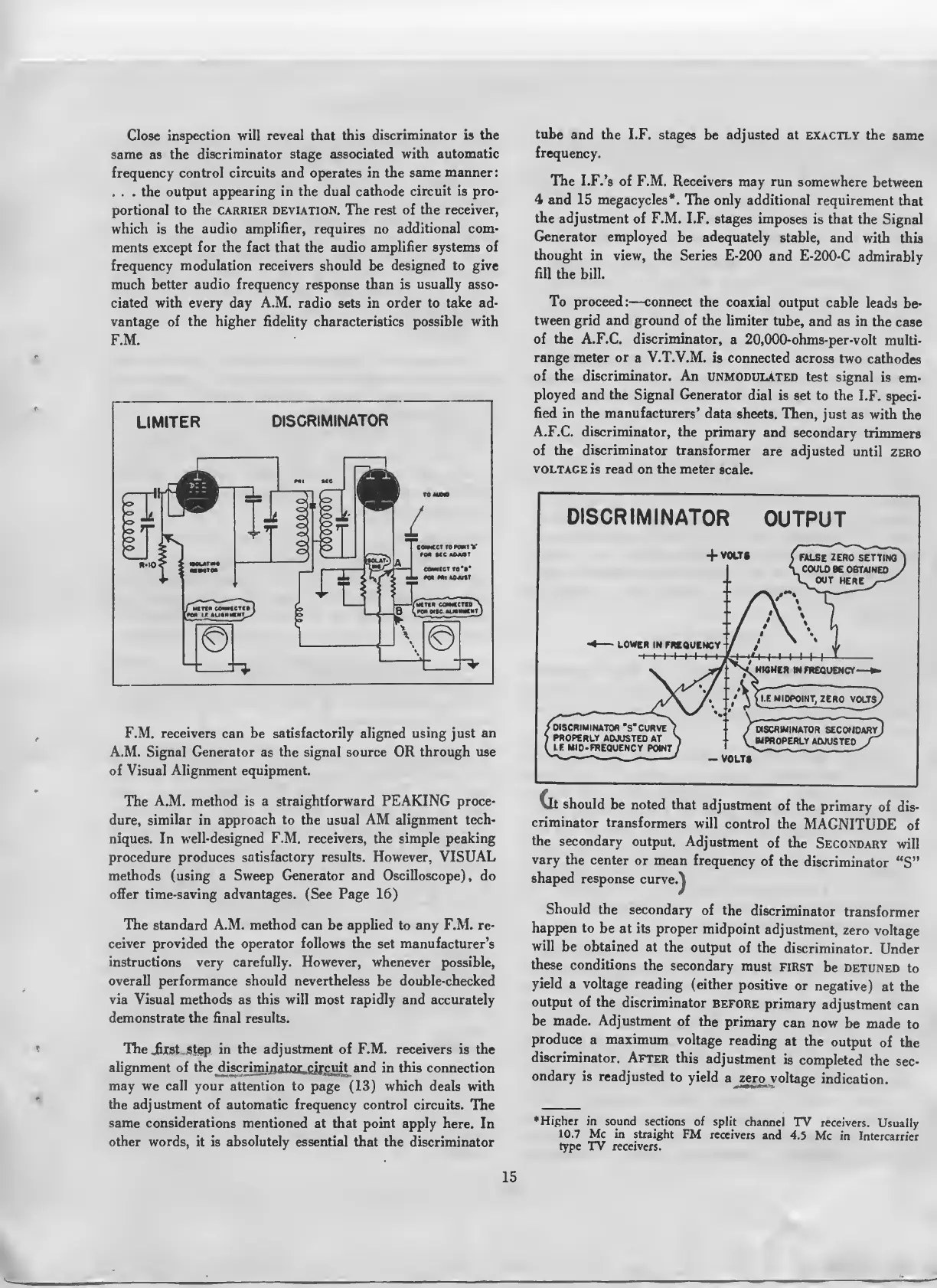
DISCRIMINATOR
OUTPUT
Clt
should
be noted
that
adjustment
of the
primary
of dis-
criminator
transformers
will
control
the
MAGNITUDE
of
the secondary
output.
Adjustment
of the
Secondary
will
vary
the
center
or mean
frequency
of
the
discriminator
"S"
shaped
response
curve.\
Should
the secondary
of the
discriminator
transformer
happen
to
be at its
proper
midpoint
adjustment,
zero
voltage
will
be
obtained
at
the
output
of the
discriminator.
Under
these
conditions
the
secondary
must
first
be
detuned
to
yield
a
voltage
reading
(either
positive
or
negative)
at the
output
of the
discriminator
before
primary
adjustment
can
be
made. Adjustment
of the
primary
can
now
be
made
to
produce
a maximum
voltage
reading
at
the
output
of
the
discriminator.
After
this
adjustment
is
completed
the
sec-
ondary
is
readjusted
to yield
a zero
voltage
indication.
Higher
in sound
sections of
split
channel
TV receivers.
Usually
10.7 Mc in
straight FM
receivers
and
4.5 Mc in
Intercarrier
type TV
receivers.
 Loading...