1-800-255-5387 • www.premier-mfg.com
premier manufacturing company
Page 2
shoe stop. You may need to push the shoe
forward to allow for clearance of the spring.
Turn the coupling back around to face the
front of it. Locate the 374 Bolt residing in the
379 Shoe and remove the 274A Locknut from
the right side. Slide the 374 Bolt out from the
left side and remove the 379 Shoe and 376
Spring from the top of the coupling opening.
5) With all parts removed from the coupling body,
clean and inspect the body for wear and/or
damage. If wear exists or damage is noted, do
not attempt to repair. DO NOT ATTEMPT WELD
REPAIR OF ANY DAMAGED AND/OR WORN
PART.
DISASSEMBLY IS COMPLETE
IMPORTANT NOTES TO CLEAN,
INSPECT & LUBRICATE:
► Use only genuine PREMIER replacement parts
on any repairs. Use of other parts, which can
have different specifications or tolerances, may
fail to alert you to non-obvious damage to the
hitch which can lead to hitch failure.
► All body holes, part holes and pins need to be
thoroughly cleaned and lubricated with a heavy
grease before the parts are reassembled. If a
bushing resides in a part, lubricate the hole prior
to installing the bushing. (DO NOT LUBRICATE
PINTLE HOOK WEAR SURFACE).
► Clean, inspect and lubricate latch components
every 90 days or sooner if required by the
operating environment.
► Clean and inspect the coupling for damage and
excessive wear prior to each and every use.
► Do not over-tighten fasteners as this may cause
damage.
ASSEMBLY
Prior to assembly, place the 2072B Bushing in the
2072 Latch. Align the latch with the upper coupling
body holes and slide the 2071 Bolt through the
holes. Rotate the latch to the closed position and
measure the gap between the latch and top of the
pintle. If the gap is 3/8” or more, the coupling body
is damaged and must be replaced. If the gap is less
than 3/8”, remove the bolt, latch and bushing and
begin assembly.
1) IF you are replacing the 279 or 379 Shoe and its
components, then determine your model number
and follow instructions for either A or B below:
Otherwise continue on to #2.
A) FOR MODELS 2200, 2300, 2400, 2400H:
Place the 266 Spring over the nipple on the
279 Shoe. Insert as assembled through the
opening at the top of the coupling and into the
cavity at the bottom. The 266 Spring should
seat into the concave cavity, which resides
below the pintle base. The 266 Spring must
be slightly compressed to align the 279
Shoe hole with the bottom body hole. From
the left side of the body, insert the 274 Bolt
(left to right) into the bottom coupling body
hole and secure on the right side with 274A
Locknut. Make certain that one of the flats of
the 274 Bolt head is flush with the flat on the
body sidewall. Rotate the 279 Shoe to verify
proper spring tension.
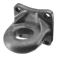
B) FOR MODEL 2300B ONLY:
Place the 376 Spring along the right side of
the 379 Shoe (see Image #1 for 379 Shoe
orientation). The hooked leg of the spring
should nest around the front neck of the
shoe, and the straight leg should be pointing
upward. Insert as assembled through the
opening at the top of the coupling and into the
cavity at the bottom. Position the coupling
as needed so that you can reach through the
back side (mounting base) opening of the
coupling. Grasp the straight leg of the 376
Spring and pull it over the shoe stop, located
on the interior sidewall of the body. (Using
a hooked tool would make this easier to
accomplish.) It is IMPORTANT to secure the
straight leg under the very bottom of the shoe
stop (see Image #3 to confirm location). Align
the bolt hole on the shoe and spring with the
bolt hole on the coupling body. Facing the
front of the coupling, insert the 374 Bolt into
the left side of the bottom coupling body hole,
and secure it on the right side with the 274A
Locknut. Make certain that one of the flats of
the 374 Bolt head is flush with the flat on the
 Loading...