EasyManua.ls Logo

Premier 2000 Series - User Manual

Premier 2000 Series
8 pages
Print Icon
To Next Page IconTo Next Page
Loading...
1-800-255-5387 www.premier-mfg.com
premier manufacturing company
Page 1
THE FIRST NAME IN QUALITY COUPLINGS
2000PK SERVICE GUIDELINES
BEFORE GETTING STARTED:
This procedure should only be performed by a
qualified mechanic.
Measure the wear on the coupling’s pintle
hook. If the wear is at or exceeds 20% of the
cross section, the coupling is considered Out of
Service. Do Not continue.
NOTE: These instructions cover complete
disassembly and assembly of ALL of the
2000 series coupling components, including
pieces not included in the 2000PK specifically.
Please follow the instructions that apply to your
replacement components.
Tools required: snap ring pliers; 1 7/16” & 1
1/16” sockets; flat-bladed screw driver.
CAUTION: When removing and replacing
snap rings the appropriate snap ring plier tools
are necessary. Do not attempt removal or
replacement without the correct snap ring plier
tools. In addition, use caution when removing
and replacing snap rings – Do not over-expand
them as damage could result. Also, when
assembling a snap ring into position - Make
certain that the snap ring is fully seated into the
groove.
Safety glasses are required for all of the
following procedures.
Prior to disassembly, familiarize yourself with the
location of all the various parts in the coupling.
This will assist in the assembly process.
See attached Image Reference Section(s)
with photos and/or drawings to identify various
product parts.
These procedures apply for all of the model 2000
Series Couplings: 2200, 2300, 2300B, 2400, &
2400H; though most of the images used in this
document are of the model 2200.
DISASSEMBLY
1) The 2000 series coupling should be positioned
upright, as if mounted, with the latch in the
closed position. See Image #2 in the Image
Reference Section; the 2072 Latch is located at
the top of the coupling.
2) Locate the 2071 Bolt, which resides within the
2072 Latch, and remove the 297 Locknut from
the right side. Slide the 2071 Bolt out from the
left side. Rotate the 2073 Latch Lock backwards
to the open position and remove the 2072A
Spring and 2072 Latch. The 2072B Bushing
should be inside of the 2072 Latch bolt hole.
3) Locate the 388 Pin, which resides within the
2073 Latch Lock, and remove the 44-62 Snap
Ring from the left side. Slide the 388 Pin out
from the right side and remove the
2073 Latch Lock; 2073A Spring; 2073B Bushing;
and 373B Spacer.
4) IF you are replacing the 279 or 379 Shoe and its
components, then determine your model number
and follow instructions for either A or B below:
Otherwise, continue on to #5.
A) FOR MODELS 2200, 2300, 2400, 2400H:
Locate the 274 Bolt, which resides within the
279 Shoe at the bottom of the coupling and
remove the 274A Locknut from the right side.
Slide the 274 Bolt out from the left side and
remove the 279 Shoe and 266 Spring.
B) FOR MODEL 2300B ONLY:
See Image #3 and position the coupling
so that you are looking at the back side
(mounting base opening). Push the straight
leg of the 376 Spring to the right and upward,
until it has gone up and over the top of the
2200
Coupling
Question and Answer IconNeed help?

Do you have a question about the Premier 2000 Series and is the answer not in the manual?

Summary

Before Getting Started

Disassembly

Important Notes to Clean, Inspect & Lubricate

Assembly

Attention!

Critical Safety and Usage Guidelines

Essential safety and usage directives for correct operation, maintenance, and transportation with Premier couplings.

Important Installation Instructions

Warranty Information

Disclaimer

Overview

The Premier 2000PK Service Guidelines manual describes the maintenance and repair procedures for the Premier 2000 Series Couplings, specifically models 2200, 2300, 2300B, 2400, and 2400H. These couplings are designed for heavy-duty towing applications, connecting a drawbar eye to a towing vehicle. The manual emphasizes that all procedures must be performed by a qualified mechanic to ensure safety and proper operation.

Function Description

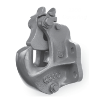
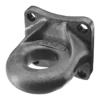
The Premier 2000 Series Couplings are critical components in towing systems, providing a secure connection between a towing vehicle and a trailer. They feature a pintle hook mechanism that engages with a drawbar eye. The coupling includes a latching system to secure the connection, with various springs, bolts, and bushings facilitating its operation. The primary function is to allow for safe and reliable towing, accommodating the forces and movements inherent in such applications.

Important Technical Specifications

The manual provides detailed instructions for the disassembly and assembly of various components, indicating specific part numbers and their roles. Key components include:

  • 44-62 Snap Ring (2): Secures pins in place.
  • 297 Locknut: Used to secure bolts.
  • 373B Spacer: Positions components within the assembly.
  • 388 Pin: Acts as a pivot or securing element for various parts.
  • 2071 Bolt: A primary fastener for the latch mechanism.
  • 2072 Latch: The main securing mechanism for the drawbar eye.
  • 2072A Spring: Provides tension for the latch.
  • 2072B Bushing: Reduces friction and wear in the latch bolt hole.
  • 2073 Latch Lock: A secondary locking mechanism for the latch.
  • 2073A Spring: Provides tension for the latch lock.
  • 2073B Bushing: Reduces friction and wear in the latch lock pin hole.
  • 266 Spring (for 2200, 2300, 2400, 2400H): Provides tension for the shoe.
  • 271 Thimble: A component related to the shoe assembly.
  • 274 Bolt (for 2200, 2300, 2400, 2400H): Secures the shoe.
  • 274A Locknut: Secures the 274 Bolt.
  • 279 Shoe (for 2200, 2300, 2400, 2400H): A wear component that interacts with the pintle hook.
  • 374 Bolt (for 2300B): Secures the 379 Shoe in model 2300B.
  • 376 Spring (for 2300B): Provides tension for the 379 Shoe in model 2300B.
  • 379 Shoe (for 2300B): A wear component specific to model 2300B.

The manual specifies a critical wear limit for the pintle hook: if wear is at or exceeds 20% of the cross-section, the coupling is considered Out of Service. Another critical measurement is the gap between the closed latch and the top of the horn or coupling ball; if this gap is 3/8 inch or more, the coupling should not be used. Fasteners must be torqued to SAE specifications, and only new fasteners should be used when mounting the coupling.

Usage Features

The coupling is designed for secure and reliable towing. Before use, it is essential to:

  • Verify that both the coupling's and drawbar eye's rated capacities meet the application requirements.
  • Ensure the coupling is not overloaded.
  • Inspect the coupling, latch, and drawbar eye for cracks, bending damage, or excessive wear.
  • Confirm the latch is securely closed and will not open during operation.
  • Always connect safety chains of adequate strength.
  • Avoid "jackknifing" the application, as this can cause severe damage to the hitch and other components, potentially leading to trailer detachment.
  • Never strike components with a hammer or other device.
  • Always verify proper operation of the latching system before driving off.
  • Understand how to properly operate and verify secure latching.

Maintenance Features

The manual outlines a comprehensive maintenance regimen to ensure the longevity and safety of the coupling:

  • Regular Inspection: Clean and inspect the coupling for damage and excessive wear prior to each and every use. Latch components should be cleaned, inspected, and lubricated every 90 days or sooner if required by the operating environment.
  • Wear Measurement: Regularly measure the pintle hook wear and the gap between the closed latch and the top of the horn or coupling ball.
  • Lubrication: All body holes, part holes, and pins need to be thoroughly cleaned and lubricated with a heavy grease before reassembly. If a bushing resides in a part, lubricate the hole prior to installing the bushing. Crucially, do NOT lubricate the pintle hook wear surface or the coupling hook/drawbar eye loop, as this can mask damage and accelerate wear.
  • Part Replacement: Use only genuine PREMIER replacement parts for any repairs. The manual explicitly warns against using non-Premier components, as this voids the warranty and can compromise the unit's integrity, leading to property damage, serious injury, or death.
  • No Welding: Welding on any coupling assembly is strictly prohibited.
  • Fastener Torque: Do not over-tighten fasteners. Use Grade-8 fasteners properly torqued to SAE specifications.
  • Spring Tension Verification: During assembly, rotate the latch lock and latch to ensure smooth, increasing spring resistance. If no resistance or binding is felt, the springs or parts are not installed correctly and require reassembly.
  • Functional Testing: After assembly, the coupling should be opened and closed several times to test for smooth and correct operation. If it does not operate properly, assistance should be sought.

The manual also includes a warning that installation must be performed by a qualified mechanic and emphasizes the importance of reading all instructions before attempting any work. It also provides a warranty statement covering defects in material or workmanship for one year, provided the product has not been misused, neglected, improperly installed, maintained, or altered without authorization.

Premier 2000 Series Specifications

General IconGeneral
BrandPremier
Model2000 Series
CategoryIndustrial Equipment
LanguageEnglish

Related product manuals