1-800-255-5387 • www.premier-mfg.com
PREMIER MANUFACTURING COMPANY
Page 7
Model 330 / 330A Hinge Assembly
INSTALLATION
bore from the opposite end of the 359 Flange
(see Figure 4). Using a rubber mallet only, tap
the taper pin into the bracket until the head of
the taper pin is flush against the bracket.
15. Place one 321D Washer onto the 321B Bolt
and slide it through the 352 Taper pin. Place
the second 321D washer and 321C Locknut
onto the end of the 321B bolt. Prior to
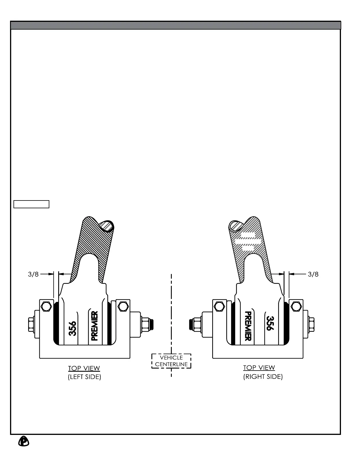
tightening, check to make sure the 3/8” gap
between the 356 Housing and 350 Bracket
exists (see Figure 1).
16. Torque the 321C Locknut to 60 ft-lbs. Test
the hinge assemblies for desired rotational
stiffness. If a stiffer hinge is desired, tighten
the 321C Locknut in 10-20 ft-lb increments.
DO NOT EXCEED 200 ft-lbs of TORQUE.
17. Tighten the 351 Bolts to 80 ft-lbs of torque.
These bolts compress the 350 Bracket,
clamping both the 359 Flange and 352 Taper
pin. Note: Both 351 Bolts must be loosened
prior to any future adjustment of the of the
321B Bolt for hinge stiffness. After adjustment,
the 351 Bolts must be retorqued to 80 ft-lbs.
18. An “IMPORTANT WARNINGS!” sticker was
enclosed. This must be attached to the front
end, adjacent to the drawbar eye, visible for the
end user to read.
2 1/2"
FRONT END
TUBE
Figure 1