Do you have a question about the PRESIDENT Randy II P and is the answer not in the manual?
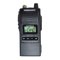
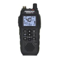
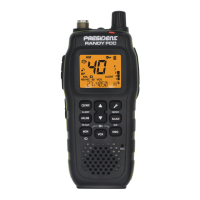
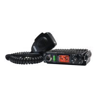
This document is a service manual for the XH9006E, RANDY II P & M 27MHz CB Radio, Ver.02, dated 2013/03/08, manufactured by Chief Tek Electronic Co., LTD. It provides comprehensive information for understanding, operating, and maintaining the device.
The XH9006E/XH9600E is a low-band VHF radio designed for AM & FM modulation, operating within a frequency range of 26.965 – 27.405 MHz. It features a double-mixer system for both FM and AM, with a 1st intermediate frequency of 10.695MHz and a 2nd intermediate frequency of 455KHz. The audio signal is connected to a loudspeaker. The local frequency is generated by a voltage-controlled oscillator (VCO) controlled by the MCU (U4) through a PLL chip (U6). The PLL OSC frequency is 10.24MHz, generated by an XA1 crystal, and the MCU clock is built-in. The transmission frequency is derived from the VCO with AM or FM modulation, then passed through an RF PA amplifier (Q1) and a low pass filter (L1-L4) to the antenna.
The receiver section incorporates an antenna low pass filter to attenuate unwanted signals in RX & TX mode, utilizing L1, L2, L3, L4, L6, and other related components. An antenna switch manages the RX/TX antenna switching, involving D1, D2, C15, C21, D4, and R3. The front end LNA circuit includes a band pass filter and LNA amplifier (L8, L10, L11, Q59, L14, L15, L16) with Q42 serving as the LNA amplifier. The 1st mixer & IF filter mixes the input signal with a local OSC signal to generate the 1st IF of 10.695MHz, using Q5, L17, R95, C130, C66, R10, which then passes through the IF filter XF1. The 1st IF amplifier & audio detect signal uses U2 (including a 2nd IF mixer, amplifier, AM/FM detect, etc.) pin 20, which goes through a 455KHz ceramic filter FA1 & discriminator Y2 to detect an AF signal out of U2 pin11 (FM) or pin14 (AM). The squelch & AGC circuit manages noise signals to the noise amplifier input (U2 pin12) and output from U2 pin13, then goes to the U1 to get the noise level and RSSI level. These levels are used to set the squelch level by MCU & AGC circuit (Q6, Q7). The AM/FM switching & speaker amplifier allows the AM/FM audio signal to be switched by Q10, Q11, then goes to the TIC1 pin23 for CTCSS tone decoder and audio process, then to the speaker amplifier (U3) through buffer amplifier (Q8) and volume controller.
The PLL circuit controls the VCO to generate the local OSC frequency for receiving and transmitting. The PLL circuit (U6) uses a 10.24MHz crystal (XA1) to generate a standard frequency. The U6 pin5 charges the pump output, connecting to VCO D22, D23 through a low pass filter R222, E11, R219,218, E10, E9, R158. The U6 pin8 is the RF input from VCO OUT (Q29). The VCO (voltage controlled oscillator) circuit includes Q44, L24, L25, D22, D23, D20, and related components. Q45 is the VCO switch to control RX/TX OSC frequency. Q9 is the ripple filter of power supply. Q28 is the RX buffer amplifier. Q3 is the TX buffer amplifier. D20 is the FM modulation diode. The PLL un-lock detect circuit involves D15, R17, R16, R221, C110, which are part of the PLL Lock detect to MCU PLL-LD pin.
AM modulation is achieved by connecting the microphone signal to U7 pin3, after an amplifier, band pass filter, and AGC circuit. It goes out through W3, Q18, Q12, Q13, Q14 to PVCC of the RF power supply. FM modulation is simpler, with the circuit going from U7 Pin 14 through C19, R230, R67, W5 to VCO D20. The TX driver & power amplifier circuit involves Q3, Q2, and Q1, which are TX driver amplifiers after the VCO switching circuit. Q1 is the TX power transistor. The TX power level has Hi & Low two power levels. The MCU APC pin is used to fine-tune the Hi power to 4W and Low power to 1W in FM mode. AM Hi power is tuned by W1 and goes through D11, D10, D9, Q12, Q13, Q14 to PVCC.
The system power supply is able to offer stable +5VDC by IC2, then IC1 is used for MCU +3.3VDC power supply.
The controlled system is managed by MCU, including low battery check, squelch level setting, PLL data, AM/FM power controlled, modulation, operating channel setting, and EEPROM data.
The radio is designed for ease of use with both AM and FM modulation. The user can adjust the squelch level, which has 6 adjustable levels, to filter out unwanted noise. The device supports a maximum of 40 channels, with a 10KHz channel step. The operating voltage range is 6.29V to 8.4V, with a nominal input voltage of 8.4VDC.
The service manual provides detailed alignment procedures for the radio.
The manual also includes detailed circuit diagrams, PCB layouts (top, bottom, and various layers), solder masks, drill drawings, and a comprehensive electronic material list with part numbers, descriptions, specifications, quantities, and locations. Mechanical explode views and material lists are provided for assembly and repair. Semiconductor lead identification and IC lead identification diagrams are also included to assist with component identification and troubleshooting.