14 www.pridemobility.com Quantum 610
V. COMFORT ADJUSTMENTS
COMFORT ADJUSTMENTS
After becoming familiar with your power chair’s operation, you may fi nd the need to make some adjustments to
increase your comfort, such as seat height and angle, armrest angle, foot platform height and angle, and controller
position. If your power chair is equipped with power positioning options, refer to the information supplied in
supplemental manuals or contact your Quantum Rehab Dealer.
WARNING! The centre of gravity of your power chair was factory set to a position that meets
the needs of the demographic majority of users. Your Quantum Rehab Dealer has evaluated your
power chair and made any necessary adjustments to suit your specifi c requirements. Do not
change your seating confi guration without fi rst contacting your Quantum Rehab Dealer.
WARNING! Some power chair components are heavy. You may need assistance to lift or carry
them. Please refer to specifi cations table for specifi c component weights before you disassemble
the power chair.
WARNING! Remove the occupant from the power chair before making any adjustments.
You may need the following to make comfort adjustments:
metric/standard socket set and ratchet
adjustable spanner
thread lock
Seat Height and Seat Angle Adjustment
You can change the seat height to one of four positions in
2.54-cm (1-in.) increments by raising the front and rear
trapeze bars. If you raise or lower only one trapeze bar (front
or rear), you can also change the seat base angle (dump).
To change the seat height:
1. Turn off the power to the controller.
2. Loosen the rear shroud fasteners and remove the rear
shroud. See fi gure 2.
3. Disconnect the controller connector(s) from the power
base. See fi gure 3.
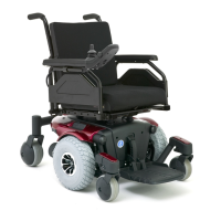
4. Flip up the seat latch safety. See fi gure 11.
5. Squeeze the seat latch and release the seat from the front
trapeze bar. See fi gure 11.
6. Slide the seat forward and remove it from the power
base.
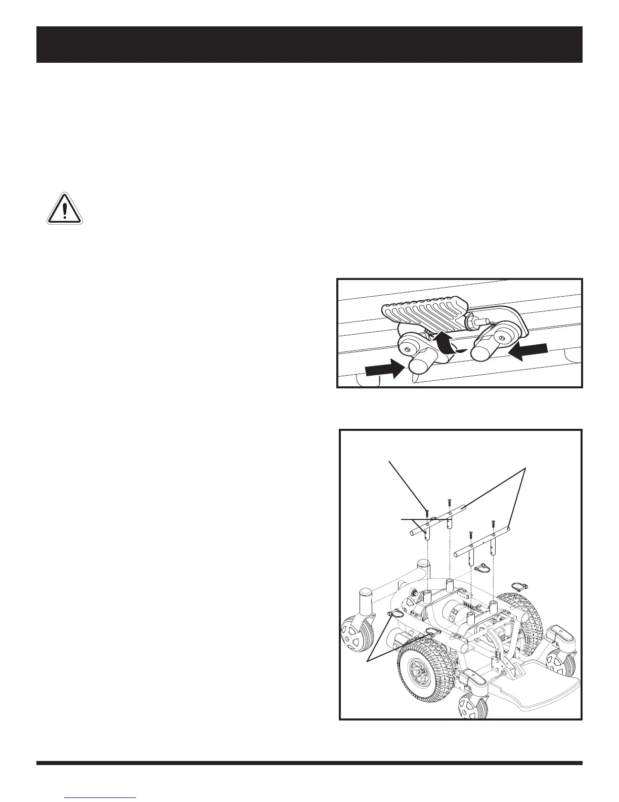
7. Loosen the screws that attach the trapeze bars to the seat
posts. See fi gure 12.
8. Remove the retaining clips that secure the seat posts to
the power base. See fi gure 12.
9. Move the trapeze bars up or down to the desired height.
10. Reinstall the retaining clips from step 8.
11. Remove each screw from the trapeze bars and apply
thread lock.
12. Reinstall each screw into the trapeze bars and tighten.
13. Reinstall the seat and fl ip down the seat latch safety.
14. Reconnect the controller connector(s) to the power base.
15. Reinstall the rear shroud and tighten the fasteners.
Figure 11. Seat Height Adjustment - Seat Latch
Safety
Figure 12. Seat Height Adjustment - Trapeze Bars
SCREWS
(2 OF 4)
TRAPEZE BARS
SEAT POSTS
(2 OF 4)
RETAINING
CLIPS
(2 OF 4)