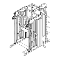
ASSEMBLY DIAGRAM 5 USE A PARTNER TO HELP WITH THIS STEP
REMEMBER: Only hand tighten all nuts and bolts until whole machine is assembled
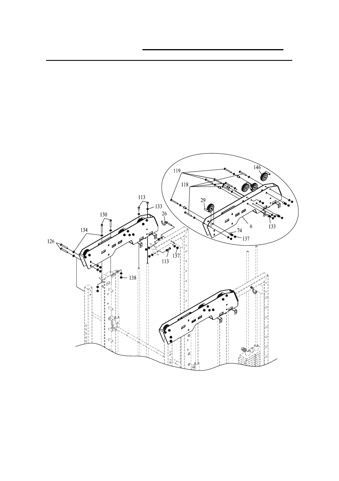
1.
(See the pulley exploded diagram for more detail.)
Attach PULLEY (146) to TOP FRAME (6) with
NYLONBUSHING(74),BOLTM10*90(119),WASHER10(133)andLOCKNUTM10(137).
2.
AttachROUNDTUBE(29)toTOPFRAME(6)withBOLTM10*85(118),WASHER10(133)and
LOCKNUTM10(137).
3.
AttachTOPFRAME(6)toADJUSTABLESLIDEFRAME&REARSLIDEFRAME(4&5)andGUIDE
ROD (10) with BOLT M12*85 (126), HEX SOCKET BOLT M12*80 (130), WASHER 12 (134),
LOCKNUTM12(138),BOLTM10*25(113)andWASHER10(133).
 Loading...