28 www.pridemobility.com Artemis
11. Use wire ties to secure the controller harness and the
manual recline lever cable to the armrests.
12. Route the controller harness to the front of the power base
and reconnect the controller. See figure 21.
To extend the controller:
1. Loosen the setscrews in the mounting block. See figure 19 or 20.
2. Slide the controller into or out of the mounting block to the
desired position.
3. Tighten the setscrews to secure the controller.
Anti-Tip Wheels
The anti-tip wheels are designed to give your power chair
increased stability on rough surfaces. The anti-tip wheels are preset
at the factory for smooth surfaces or indoor use only. If you plan
on using your power chair on rough surfaces, it may be necessary
to adjust the anti-tip wheels to better suit your needs. The anti-tip
wheels may need adjustment if either of the following occur:
When accelerating, your power chair tips rearward
excessively.
The anti-tip wheels constantly rub the ground.
WARNING! Consult your Quantum Rehab
Dealer before attempting to change the anti-
tip wheel height! Changing the anti-tip wheel
height affects handling under deceleration!
WARNING! The higher you raise the anti-tip
wheels, the more you increase your power
chair’s tendency to tilt rearward when
accelerating. You can compensate for this by
having your Quantum Rehab Dealer make a
small adjustment to the pre-programmed
acceleration setting in the controller or by
adjusting the seat assembly.
WARNING! The anti-tip wheels may cause
trouble when ascending or descending a kerb
if they are not adjusted correctly. Contact
your Quantum Rehab Dealer for more
information.
IV. COMFORT ADJUSTMENTS
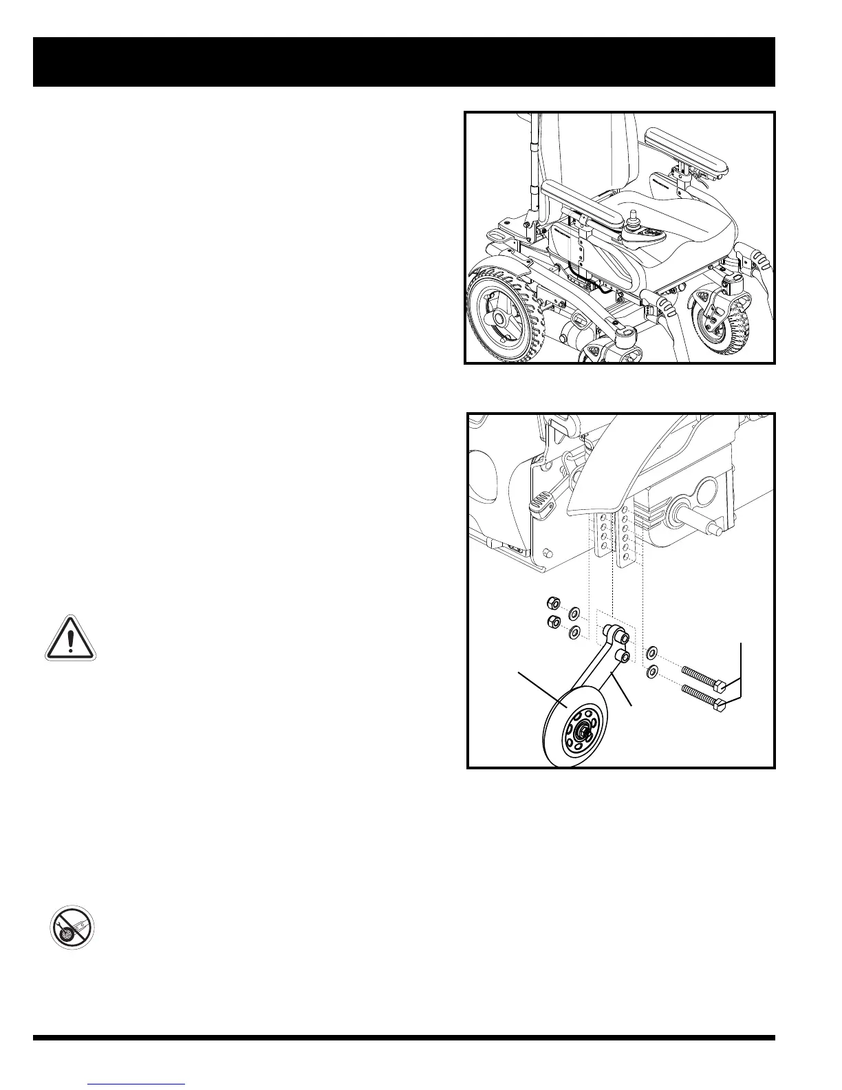
Figure 21. Controller Harness Routing
Figure 22. Anti-Tip Wheel Assembly
ANTI-TIP
WHEEL
BRACKET
BOLTS
ANTI-TIP
WHEEL
To adjust the anti-tip wheels:
1. Remove both bolts from the ani-tip wheel bracket. See figure 22.
2. Raise or lower the anti-tip wheel in 1.25 cm (0.5 in.) increments by aligning the appropriate adjustment holes.
See figure 22.
3. Reininstall and tighten both holes.
4. Raise or lower the other anti-tip wheel so that it is at the same height.
PROHIBITED! Do not remove the anti-tip wheels.
NOTE: Each drive tyre must be inflated to the the psi/bar/kPa air pressure rating indicated on each tyre in
order for the anti-tip wheels to be properly adjusted. The user must also be seated in the power chair in order
to properly adjust the anti-tip wheels.