Artemis www.pridemobility.com 27
Controller Position
You can move the controller in toward or out away from the
armrest, or change the position of the controller for either
left-hand or right-hand use.
MANDATORY! Prevent controller harness
damage! Avoid routing the controller
harness on the outside of the armrest pad.
Route the harness under the armrest or
toward the inside of the armrest pad. Use
correct tie-down points for the controller
harness to prevent the harness from getting
caught in the drive tyres, pinched in the
seat frame or damaged when passing
through doorways.
NOTE: Your controller will be attached either by a mount-
ing block or a figure 8 assembly. Be sure to follow the cor-
rect set of instructions below when changing the position
of your controller.
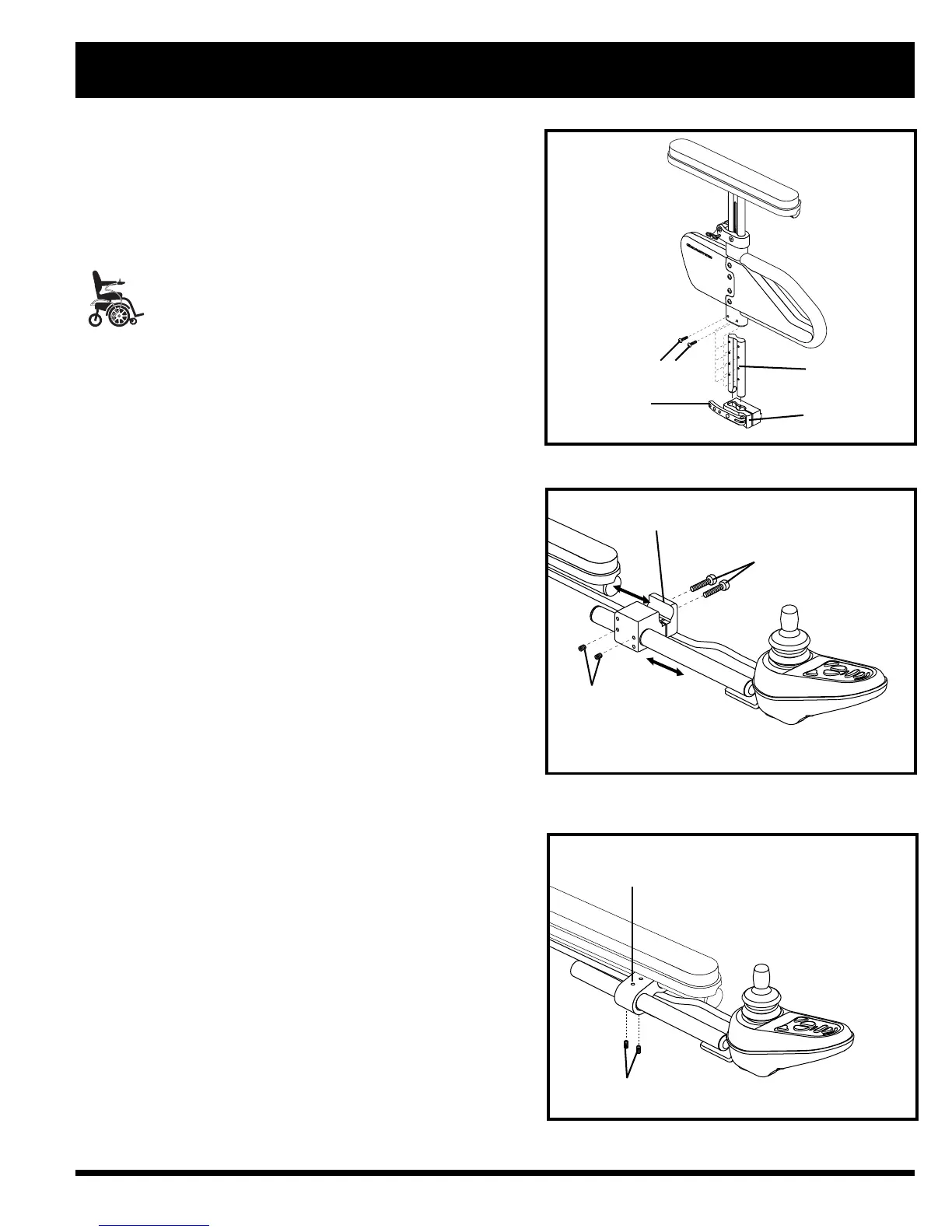
To change the controller position in a mounting block:
1. Turn off the power to the controller.
2. Unplug the controller connector from the front of the
power base. See figure 6.
3. Remove any wire ties securing the controller harness to
the armrest.
4. Loosen the mounting screws in the controller mounting
block. See figure 19.
5. Move the controller mounting block and controller to
the other armrest and tighten the mounting screws.
6. Use wire ties to secure the controller harness and the
manual recline lever cable to the armrests.
7. Route the controller harness to the front of the power
base and reconnect the controller. See figure 21.
To change the controller position in a figure 8 assembly:
1. Turn off the power to the controller.
2. Unplug the controller connector from the front of the
power base. See figure 6.
3. Remove any wire ties securing the controller harness to
the armrest.
4. Loosen the setscrews on the figure 8 clamp assembly
located on the armrest. See figure 20.
5. Slide the controller out of the loosened clamp assembly.
6. Loosen the setscrews on the clamp assembly on the
other armrest.
7. Remove the manual recline lever assembly and insert it
into the clamp assembly on the opposite armrest. See
figure 10.
8. Tighten the setscrews to secure the manual recline lever
assembly in the figure 8 clamp.
9.
Insert the controller into the remaining open clamp
assembly.
10. Tighten the setscrews to secure the controller in the
figure 8 clamp.
IV. COMFORT ADJUSTMENTS
Figure 18. Armrest Bottom Height Adjustment
BUTTON HEAD SCREWS
ARMREST LOCK
LEVER
ARMREST LOCK
DETENT BAR
Figure 19. Controller Position (Standard
Mounting Block Shown)
MOUNTING BLOCK
MOUNTING SCREWS
SETSCREWS
Figure 20. Controller Position (Figure 8 Assembly)
FIGURE 8 CLAMP ASSEMBLY
SETSCREWS