513289 PUBLICATION DATE 07/04 INSTALLATION AND MAINTENANCE MANUAL 15
MACHINE
SUPPLY
VOLTAGE
HEATING TYPE MAX. CURRENT (A)
steam 29,00
electrical 54 kW 99,00
3AC 400V
electrical 72 kW 128,00
steam 50,00
electrical 54 kW 175,00
90 KG / 198 LB
3AC 230V
electrical 72 kW 220,00
3AC 400V
steam 49,00
140 KG / 308 LB
3AC 230V
steam 85,00
3AC 400V
steam 59,00
180 KG / 396 LB
3AC 230V
steam 125,00
Tab. 4.4.C
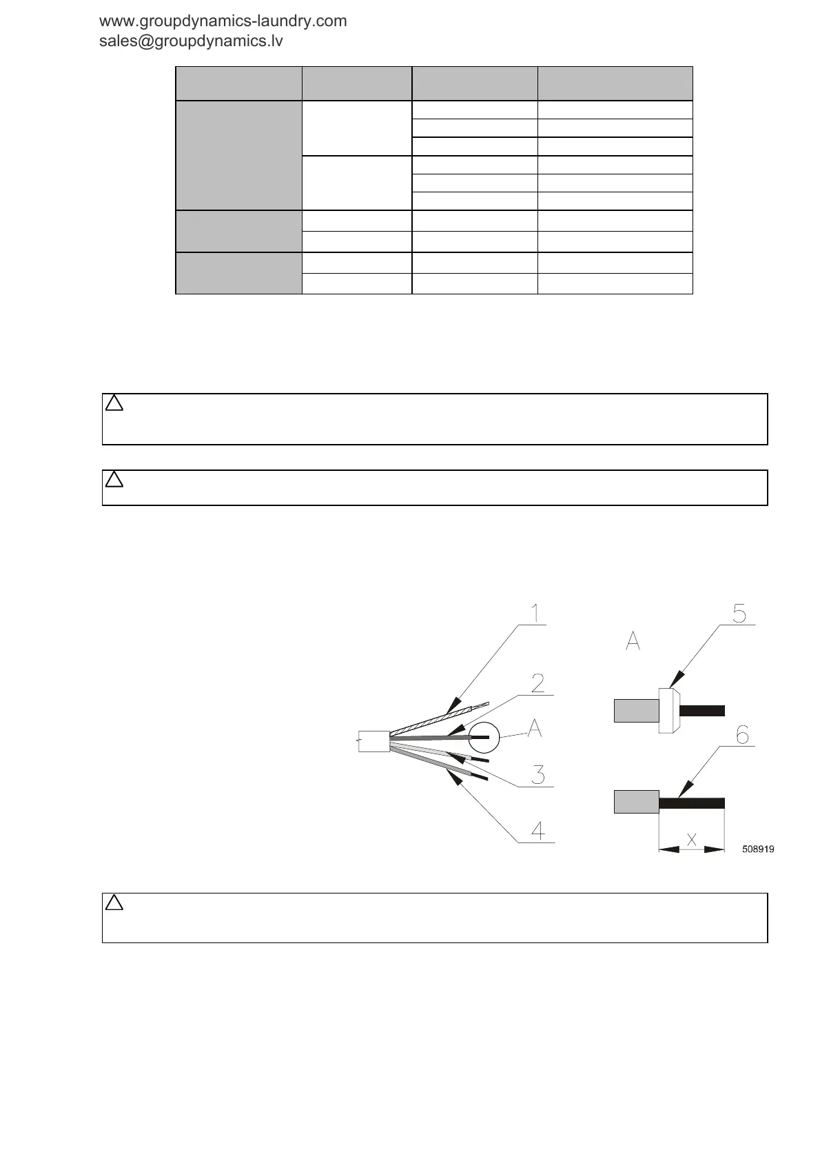
SUPPLY CABLE CONNECTION TO THE MACHINE
CABLE PREPARATION
Use a cable or cord with copper conductors for the connection. Adapt the conductor ends according the fig. 4.4.B.
WARNING !
THE PROTECTIVE CONDUCTOR MUST BE LONGER SO THAT WHEN THE CABLE IS PULLED OUT
ACCIDENTALLY, THIS CONDUCTOR IS DISCONNECTED AS THE LAST ONE!
WARNING !
THE WASHER EXTRACTOR IS INTENDED TO BE PERMANENTLY CONNECTED TO FIXED WIRING.
When using the cable (hard copper conductors), strip individual cores in such way to avoid the protrusion
of a stripped part from the terminal when the conductor is connected into the device, fig.4.4.B - pos.6) -
dimension X. When using a cord (stranded copper conductors), the individual cores can be stripped in the
same way as in the case of a cable, or you can use moulding tubes (5).
To avoid a contact to a part under tension after the conductor connection even when the main switch is off,
use tubes with an insulated neck on the conductors ends.
1. Protection conductor
2. Phase conductor
3. Phase conductor
4. Phase conductor
5. Moulding tube
6. The stripped length of conductors
Fig. 4.4.B Adaptation of conductor ends
of supplying cable
CONNECTING POINT
Directly on the connectors of the main switch, which is placed in the machine distributor.
WARNING !
MAIN SWITCH MUST BE IN POSITION OFF (0) WHEN YOU OPEN THE DOOR OF DISTRIBUTOR.
OTHERWISE THERE IS A RISK OF ITS DAMAGE !
The cable can be attached to the machine from a cable channel (from below). If the cable is attached from
above, it is recommended to make a sag on the cable in front of the entry into the cable bushing, fig.4.4.C, pos.4.
In this way an ingress of condensed water into the bushing or the machine can be avoided. When the cable is
pushed through the bushing (3), tighten the sealing nut of the bushing. By this way the rubber ring in the bush
is pressed, thus securing the cable mechanically and against water. The supply cable is connected to the
main switch of the machine (1). The phase terminals are marked by U, V, W (L1, L2, L3). ). Connect the
protective conductor directly on the protective terminal which is located near connectors U,V,W. The
terminal has been marked as PE.
!
!
!
www.groupdynamics-laundry.com
sales@groupdynamics.lv