EasyManua.ls Logo

Primus PSS500 - User Manual

Primus PSS500
6 pages
Print Icon
To Next Page IconTo Next Page
Loading...
DID DID
DID DID
DID
YY
YY
Y
OU KNOOU KNO
OU KNOOU KNO
OU KNO
W?W?
W?W?
W?
PRIMUS
STERILIZER Company, LLC • 6565 South 118
th
Street • Omaha, NE 68137• Phone (402) 344-4200 • Fax (402) 344-4242
Page 1 of 6
NO: 258 April 30, 2014
PSS500 CONTROL BOARD JUMPERS - FIELD CONFIGURATION
®
Overview
The PSS500 control system uses jumpers to configure the control board for the
specific configuration of options and relays being used on a sterilizer.
The configuration is based on the sterilizer purchase order options and the
proposed purpose (Healthcare, BioPharma, Laboratory, Vivarium, etc.) for the
sterilizer.
The jumper configuration is set by PRIMUS using the electrical drawings and
specified Opto-22 relay board configuration for the sterilizer being built.
The PSS500 control board and jumper configuration are further checked during the
Factory Acceptance Testing (FAT).
Caution
Under normal conditions, there IS NO reason to adjust or re-configure
jumpers on a PSS500 control board. Unless specifically directed to
alter the jumpers by PRIMUS, field maintenance IS NOT required on
these settings.
Returning a Control Board to PRIMUS
If a control board is returned to PRIMUS for testing due to some kind of problem, it
is important the jumpers not be altered prior to sending the board back to PRIMUS.
This will allow PRIMUS to test the board as it was used in the field.
When replacing a PSS500 control board (PRIMUS PN 200128), PRIMUS will
configure the jumpers before sending the board to the field. The respective
configuration will be based on the sterilizers Job Number.

Other manuals for Primus PSS500

Question and Answer IconNeed help?

Do you have a question about the Primus PSS500 and is the answer not in the manual?

Summary

Overview of PSS500 Control Board Jumpers

Returning a Control Board to PRIMUS

Field Configuration Procedures

Spare Control Boards Configuration

Describes jumper placement for spare boards and field verification during installation.

Configuring Jumpers in the Field

Advises against field configuration due to complexity and ESD risks, emphasizing strict adherence to procedures.

Step-by-Step Jumper Configuration Process

Board Removal and Preparation

Details steps for safely removing the SBC196 board, noting orientation and handling precautions.

Jumper Setting and Re-assembly

Guides on setting jumpers, documenting placement, and re-assembling the board with stand-offs and sockets.

Final Steps and Verification

Covers final board seating, connecting cables, verifying connections, and restoring power.

Additional Information and References

Overview

The provided document, "DID YOU KNOW? NO: 258," dated April 30, 2014, describes the PSS500 Control Board Jumpers - Field Configuration for a sterilizer control system manufactured by PRIMUS STERILIZER Company, LLC. This document, spanning six pages, details the function, configuration, and maintenance aspects of the PSS500 control board, specifically focusing on its jumpers.

Function Description

The PSS500 control board is a critical component within a sterilizer control system. Its primary function is to manage the sterilizer's operations by configuring various options and relays. This configuration is achieved through the strategic placement of jumpers on the control board. The specific jumper configuration dictates how the sterilizer operates, tailored to its intended purpose (e.g., Healthcare, BioPharma, Laboratory, Vivarium) and the options specified in the sterilizer's purchase order. The board works in conjunction with Opto-22 relay boards, and its jumper settings determine whether each of the 24 I/O (Input/Output) channels functions as an input or an output. A shorting block on a jumper sets the I/O as an Output, while an open jumper sets it as an Input.

Important Technical Specifications

The document highlights that the PSS500 control board (PRIMUS PN 200128) is designed to be configured for specific sterilizer setups. There are 24 jumpers, labeled A through X, which correspond to Opto22 modules 0 through 23. These jumpers are located under the microcontroller board (SBC196 board) and are crucial for defining the I/O functionality. The configuration is initially set by PRIMUS based on electrical drawings and the specified Opto-22 relay board configuration for the sterilizer being built. This initial setup is further verified during Factory Acceptance Testing (FAT).

Usage Features

The PSS500 control board is an integral part of the sterilizer's control system, enabling it to perform its sterilization cycles according to predefined parameters. The jumper configuration allows for customization of the sterilizer's functionality to meet diverse application requirements.

Configuration:

  • Initial Configuration: The jumper configuration is initially set by PRIMUS during manufacturing, based on the sterilizer's purchase order and intended use. This ensures the sterilizer is ready for its specific application upon delivery.
  • Field Configuration (Not Recommended): While possible, configuring jumpers in the field is generally not recommended by PRIMUS due to its complexity and the need for strong attention to detail and electrostatic discharge (ESD) practices. However, in rare situations where field configuration is necessary, a detailed procedure is provided.
  • Spare Control Boards: If a control board is ordered as a spare (for ASA or end-user customer stock), PRIMUS supplies it with a standard jumper placement. The final configuration must then be made or verified in the field during installation to match the specific sterilizer's requirements.

Safety and Best Practices:

  • ESD Protocol: When handling the control board, especially during field configuration, it is imperative to follow standard ESD protocol to prevent damage to sensitive electronic devices. ESD, a sudden flow of electricity, can occur even without being seen or heard, yet it can cause significant damage.
  • Documentation: Taking reference photographs before and after altering jumper settings is highly recommended. This helps in re-assembling the boards correctly and provides a visual record of the configuration.
  • Caution with Jumpers: Care must be taken when setting and removing jumpers to avoid bending the jumper pins, which could lead to damage or improper connections.

Maintenance Features

The document provides clear guidelines regarding the maintenance and handling of the PSS500 control board, particularly concerning its jumpers.

Jumper Configuration Maintenance:

  • No Field Adjustment Under Normal Conditions: Under normal operating conditions, there is explicitly "NO reason to adjust or re-configure jumpers on a PSS500 control board." Field maintenance is not required on these settings unless specifically directed by PRIMUS. This emphasizes the stability and pre-configured nature of the board.
  • Returning a Control Board to PRIMUS: If a control board is returned to PRIMUS for testing due to a problem, it is crucial that the jumpers are not altered prior to sending the board back. This allows PRIMUS to test the board in its "as-used" state in the field, aiding in accurate diagnosis.
  • Replacement Boards: When replacing a PSS500 control board (PN 200128), PRIMUS will pre-configure the jumpers based on the sterilizer's Job Number before shipping the board to the field. This ensures that the replacement board arrives with the correct settings for the specific sterilizer.

Procedure for Field Configuration (if necessary): The document outlines a detailed 14-step procedure for configuring the jumpers in the field, which includes:

  1. Power Off: Ensuring the control box is turned off.
  2. Ribbon Connector Removal: Carefully removing the top ribbon connector from the SBC196 board, noting its orientation.
  3. Board Disassembly: Loosening and removing the four small nuts and nylon washers securing the SBC196 board, and carefully lifting the SBC196 board to disengage it from the bottom board. This step requires careful handling to avoid losing parts or bending pins.
  4. Jumper Access: Placing the SBC196 board aside to expose the I/O jumpers on the interface control board.
  5. Jumper Configuration: Setting the jumpers to match the sterilizer's configuration, referring to electrical diagrams or existing board configurations (if replacing). Reference to other PRIMUS "DID YOU KNOW?" documents (DYK #202 and DYK #238) is provided for additional guidance on jumper configuration and understanding.
  6. Reassembly: Carefully re-orienting and pressing down the SBC196 board to engage the pins and mounting sockets, attaching the nuts and washers, and re-attaching the ribbon cable.
  7. Verification: Verifying all connections are secure.
  8. Power On: Returning power to the control board.

This comprehensive guide ensures that even in rare instances of field configuration, the process is followed meticulously to maintain the integrity and functionality of the PSS500 control board.
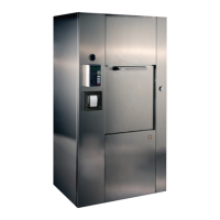
Primus PSS500 Specifications

General IconGeneral
BrandPrimus
ModelPSS500
CategoryLaboratory Equipment
LanguageEnglish