11
56713B/K2079B
Revised
2.19.15
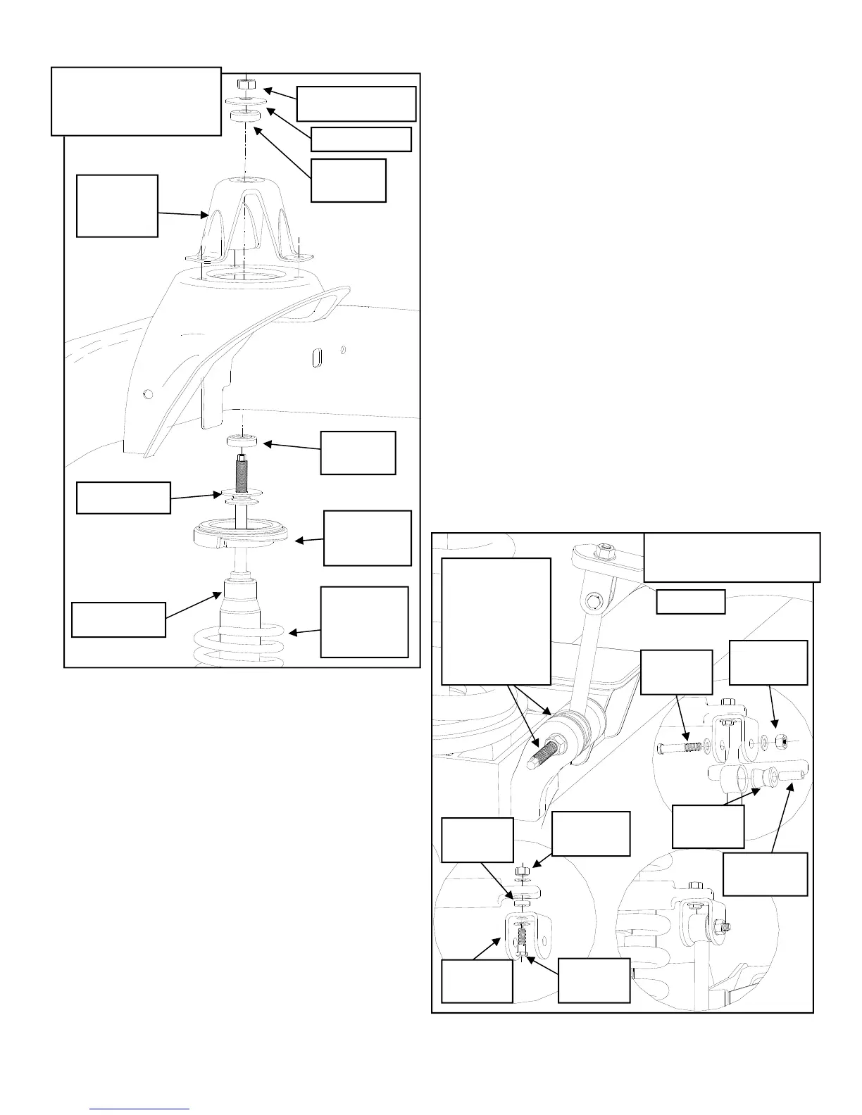
ILLUSTRATION 7.
40. Rotate the tie rod at the pitman arm 1/2
turn and attach it to the bottom of the new
pitman arm. Torque nut to 45 ft-lbs.
41. Assemble and install to the axle the
SWAY BAR LINK 90-2357 with the bush-
ings and P-843 hardware from pack 90-
6312.
NOTE: Some models may have a
14mm lower sway bar hole. If so, use the
14mm bolts and hardware from pack 90-
6430, lower bushings and sleeves from
pack 90-6242 on the bottom to attach the
links to the axle.
42. Use the 3/8” X 1 1/2” bolt and 3/8” wash-
ers and nuts from 90-6024 to attach the
90-1010 to the sway bar end. Use the
3/8” X 2 1/2” hardware from 90-6024 to
attach the 90-2357 to the 90-1010. See
ILLUSTRATION 8.
43. Repeat on the other side of the vehicle.
44. Install the hose clamps and screws from
hardware pack PN 90-6029 to the brake
lines.
45. Bolt the front brake line extension brack-
ets PN 90-1539 to the original OE brake
line bracket holes, on the front axle brack-
ets, using the previously removed OE
bolts.
46. Secure the OE brake lines to the brake
line extension brackets PN 90-1539 using
the supplied 5/16” X 1” bolt and hard-
ware.
47. Install your wheels and tires and lower the
vehicle to the ground. Tighten the lug nuts
to 90 ft-lbs.
3/8”
Hardware
3/8” X 2
1/2” Bolt
45359
Bushing
61150 3/8”
Sleeve
3/8”
Hardware
3/8” X 1
1/2” Bolt
90-1010
End Link
Sway Bar
90-2039
Spacer
ILLUSTRATION 8
Sway Bar End Link
P-843
Spacer Pack
OR
Hardware
From Packs
90-6430 and
90-6242
SHOCK
UPPER
SHOCK
BRACKET
COIL
ISOLATOR
RETAINER
SHOCK
BUSHING
SHOCK NUT
ILLUSTRATION 7
Coil Spring/Shock
Install
SHOCK
BUSHING
56160 or
56170 COIL
SPRING
RETAINER