EasyManua.ls Logo

Pro-face GP-3750T - Page 26

Pro-face GP-3750T
29 pages
Print Icon
To Next Page IconTo Next Page
To Previous Page IconTo Previous Page
Loading...
Chapter 4 Communication with Device/PLC
4.1. Shapes and Communication method of COM ports
GP-3750T
SP-5B00
(Standard box)
COM1
D-Sub9 pin (plug)
RS-232C/422/485
D-Sub9 pin (plug)
RS-232C
COM2
D-Sub9 pin (socket)
RS-422/485
D-Sub9 pin (plug)
RS-422/485
When both the COM1 port and the COM2 port have the RS-422/485 setting,
RS-422/485 cannot be used for COM1 with SP-5B00(Standard Box). In this case,
replacement to SP-5B10(Power box) is required.
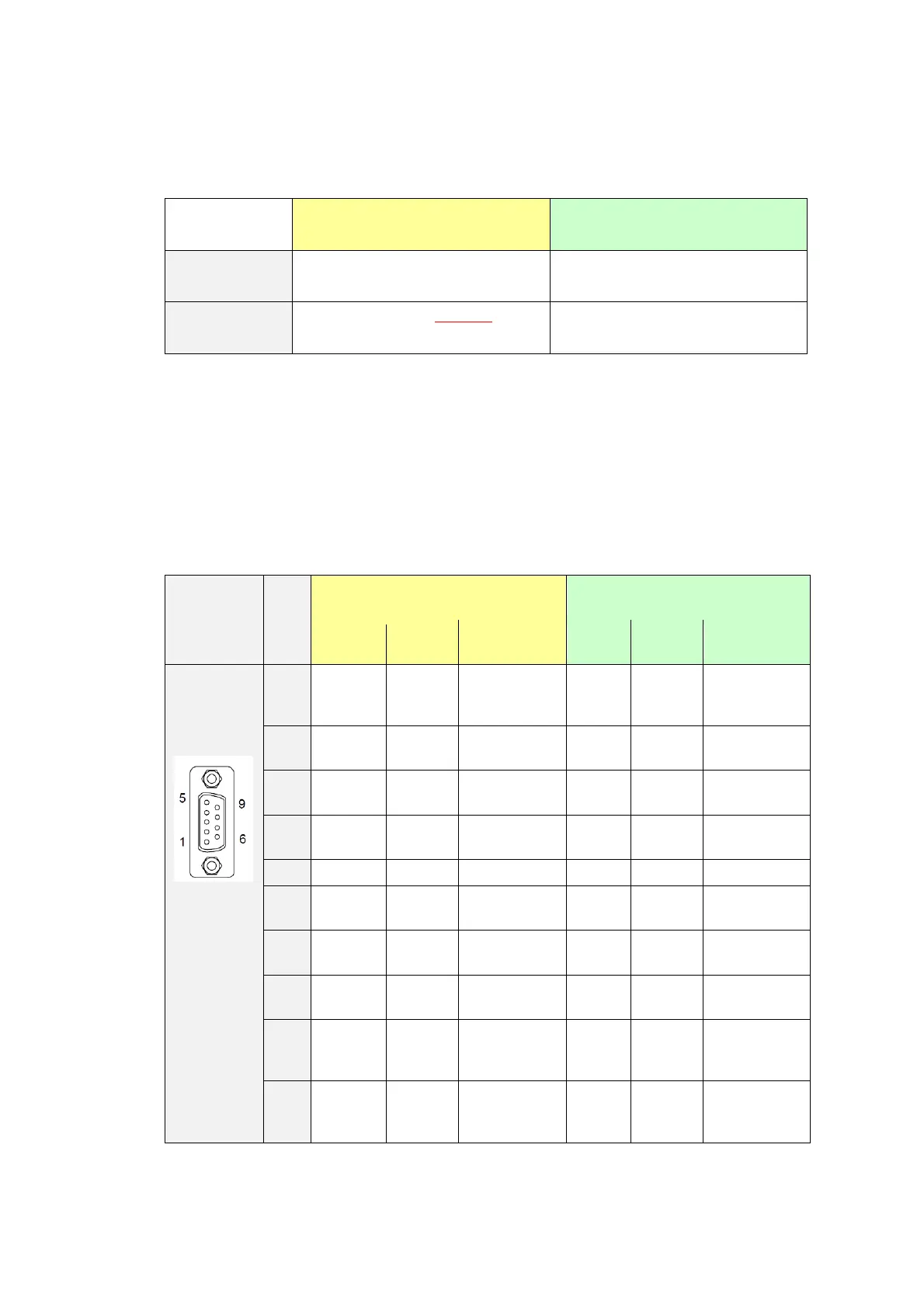
4.2. Signals of COM ports
At the time of RS-422/485 communication, the signal and the pin array differ
between the COM2 port on GP-3750T and the COM2 port on SP-5B00 (Standard
box).
Pin
Arrangement
Pin
No.
GP-3750T
SP-5B00 (Standard box)
Signal
Name
Direction
Meaning
Signal
Name
Direction
Meaning
1
TRMRX
-
Termination
(Receive
side:100Ω)
RDA
Input
Receive Data
A (+)
2
RDA
Input
Receive Data
A (+)
RDB
Input
Receive Data
B (-)
3
SDA
Output
Send Data A
(+)
SDA
Output
Send Data A
(+)
4
RS(RTS)
Output
Request for
Send
ERA
Output
Data Terminal
Ready A (+)
5
SG
-
Signal Ground
SG
-
Signal Ground
6
VCC
*1
-
+5V±5%
output 0.25A
CSB
Input
Send Possible
B (-)
7
RDB
Input
Receive Data
B (-)
SDB
Output
Send Data B
(-)
8
SDB
Output
Send Data B
(-)
CSA
Input
Send possible
A (+)
9
TRMTX
-
Termination
(Receiver
side: 100Ω)
ERB
Output
Data Terminal
Ready B (-)
Shell
FG
-
Frame Ground
(Common with
SG)
FG
-
Frame Ground
(Common
with SG)

Related product manuals