EasyManua.ls Logo

Pro-face GP37W2-BG41-24V User Manual

Pro-face GP37W2-BG41-24V
10 pages
To Next Page IconTo Next Page
Page #1 background imageLoading...
Page #1 background image
When connecting the
GP37W2-BG41-24V(hereafter referred to as the
"GP")'s
power cord terminals to the power terminal block, check first
that the GP power supply is completely turned OFF, via a breaker, or
similar unit.
Do not use power beyond the GP's specified voltage range. Doing so
may cause a fire or an electric shock.
Do not modify the GP's design, since it may lead to a fire or an electric
shock.
Do not use the GP in an environment where flammable gases are
present, since operating the GP may cause an explosion.
If the GP's lithium battery
*1
is incorrectly replaced (i.e. its + and – sides
are reversed), it may explode. Therefore, please contact your local GP
distributor prior to changing the battery.
Do not use GP touch panel switches in life-threatening or important
disaster prevention situations. For safety related switches, such as
an emergency stop switch, be sure to use a separate mechanical switch.
To prevent operator injury or machine damage, be sure to design your
system so that machinery will not malfunction due to a communication
fault between the GP and its host controller.
The GP is not appropriate for use with aircraft control devices, aerospace
equipment, central trunk data trans-mission (communication) devices,
nuclear power control devices, or medical life support equipment, due to
these devices inherent requirements of extremely high levels of safety
and reliability.
When using the GP with transportation vehicles (trains, cars and ships),
disaster and crime prevention devices, various types of safety equipment,
non-life support re-lated medical devices, etc. redundant and/or failsafe
sys-tem designs should be used to ensure the proper degree of reliability
and safety.
GP Usage Cautions
To prevent touch panel damage, do not strike the panel face with a
hard or heavy object, or push hard on the panel face.
Do not install the GP where the temperature will exceed its specified range.
Do not allow water, liquids or metal particles to enter the GP. Any of
these can lead to a malfunction or short circuit.
Avoid installing the GP where sudden, large changes in temperature
may occur. These changes may cause condensation to form inside
the unit, possibly causing the GP to malfunction.
Do not install the GP where its ventilation holes may be blocked. If
these holes are blocked, excessive heat will build up inside the GP.
Do not install or store the GP :
- Where high levels of dust exist or in direct sunlight.
- Where either strong shocks or excessive vibration may occur.
- Where chemicals or chemical fumes are present.
- Near high temperature equipment.
Do not use paint thinner or organic solvents to clean the GP's case or
screen.
Be sure to back up all GP data regularly.
After turning the GP OFF, be sure to wait a few seconds before turning
it ON again. If the GP is re-started too quickly, it may not start up cor-
rectly.
WARNINGS
*1 This mark is applicable only in Taiwan.
Question and Answer IconNeed help?

Do you have a question about the Pro-face GP37W2-BG41-24V and is the answer not in the manual?

Pro-face GP37W2-BG41-24V Specifications

General IconGeneral
Touch TypeAnalog Resistive
Power Supply24V DC
Operating Temperature0 to 50 °C
Display TypeTFT Color LCD
Storage Temperature-20 to 60 °C
Resolution800 x 480 pixels
Communication PortsRS-422/485, USB
Protection RatingIP65

Summary

General Safety Warnings

Electrical and Environmental Hazards

Warns about voltage, modification, flammable gas environments, and battery replacement risks.

Operational and Application Constraints

Advises against use in critical situations, notes communication fault risks, and unsuitable applications.

GP Usage Cautions

Panel Care and Environmental Handling

Guidelines for touch panel care, temperature extremes, liquids, ventilation, and dusty environments.

Cleaning and Restart Procedures

Instructions on cleaning with solvents and proper restart timing after shutdown.

Certification and Compliance

UL/c-UL (CSA) Application Notes

Details UL/c-UL recognition and conformance to specific safety standards for IT equipment.

CE Marking and EMC Directives

States CE marking compliance with EMC directives EN55011 class A and EN50082-2.

CNS Application Notes

CNS Standard Compliance

Indicates compliance with CNS 13438 (Class A device) and potential RF interference in home use.

Package Contents and Revision Information

Included Items and Optional Accessories

Lists package contents and available optional items such as user manuals and software.

Revision Information Details

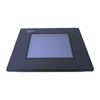
Explains how to find the unit's revision character on the rear Pro-face label.

Parts Names and Functions

Component Identification

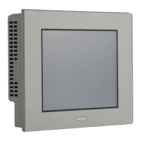
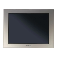
Identifies and describes the Display, Touch Panel, Power Lamp, Terminal Block, and interfaces.

Dimensions

Unit Size Specifications

Provides physical dimensions (Top, Front, Side views) in mm and inches for panel mounting.

Serial Interface Details

Pin Assignment and Signal Descriptions

Details the pinout for RS-232C/RS-422 serial interface, including signal names and meanings.

Serial Interface Precautions

Port Connectivity and VCC Notes

Emphasizes grounding for RS-485/RS-422 port and careful use of the VCC pin.

Cable Configuration and Buzzer Output

Guides on RS-232C/RS-422 cable wiring and the external buzzer output circuit.

Installation Procedures

Gasket, Panel Mounting, and Fasteners

Instructions for gasket positioning, cutting panel holes, and attaching installation fasteners.

Fastener Torque Specification

Specifies the recommended torque for installation fasteners to ensure a proper seal.

Wiring and Grounding

Power Wiring Safety and Precautions

Covers power supply connection, DC24V input, breaker switch use, and FG terminal grounding.

Ring Terminal Usage Guidelines

Provides recommendations for ring terminal size and type for power connections.

Power Cord Connection and Signal Lines

Power Cord Connection Steps

Follows sequential steps for safely connecting the GP's power cord to the terminal block.

Grounding and Signal Line Separation

Ensures exclusive grounding for FG terminal and separation of signal lines from power cables.

Maintenance and Inspection

Cleaning and Panel Operation Guidelines

Advises on proper cleaning methods and careful operation of the touch-screen panel.

Related product manuals