EasyManua.ls Logo

PRO.SIS.TEL. PST-1524TV - User Manual

PRO.SIS.TEL. PST-1524TV
4 pages
Print Icon
To Next Page IconTo Next Page
Loading...
Multi-band V solid dipole 40-20-15-10m (6m) – V2.0E
PST-1524TV
Assemblyng instructions:
The antenna can be assembled in different ways:
Assemble it on two sawhorses and then carry it on the mast or pre-assemble the elements and then complete
the assembly on the mast.
In both cases it is preferable to prepare before the elements and then the main plate assembly.
Extracting elements from the carton box, you will find the element tubes as pre-assembled elements, in a
telescopic set. Tilt the tube set, make sure that all heads of each diameter escape from the main pipe.
Do not forget to lubricate the thread of steel bolts, if dry may stiff them.
Place the element on a plan, and begin to assembly the smaller diameter,
Align the hole of the inner tube with hole of the outer tube. The fastening of the elements takes place by
inserting the bolt from the larger hole so that the cylindrical bolt head pass thoroughly and rests on the inner
tube fig.2.
Some sections are multi-perforated to facilitate the adjustment, always start from the center hole, and then
shorten or lengthen it if antenna is too long or too short.
Using the same technique, extract and splicing all sections and traps.
Tighten the nut. Make sure that all bolts heads are on the same side.
Insert the set of traps (10m on the inner side, 15m in the middle and finally 20m trap with the tip of
40m end. Even if traps set is already pre-assembled, the joints inside them have the multi drilling, if
necessary to remove the junction concerned and move to the hole that appears to be most suited to
the best resonance.
Longer antenna lower the resonance, shorter antenna increase the resonance. In both cases will have
effect on the others lower bands. Start the eventual calibration always starting from the highest
frequency (10m - 15m - 20m - 40-).
Any drainage holes present on the traps, at the end of assembly should be down side.
Do not seal traps or tube joints. Antenna must breath to prevent damages due condensation.
Question and Answer IconNeed help?

Do you have a question about the PRO.SIS.TEL. PST-1524TV and is the answer not in the manual?

Summary

Antenna Assembly Instructions

Element Attachment and Fastening

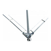
Details on attaching and fastening antenna elements using bolts and nuts, ensuring proper alignment.

Trap Installation and Tuning

Guidance on inserting traps and adjusting element length to achieve optimal resonance on various bands.

Balun Connection

Instructions for connecting a 1:1 balun to the dipole center using short wire jumpers for best resonance.

Installation and Final Checks

Post-Assembly Tightness Check

Ensuring all nuts are tight after completing the tune-up process for secure assembly.

Antenna Mounting Recommendations

Advice on mounting the antenna relative to other antennas or ground for optimal performance.

Technical Specifications

Operational Bands and Power Rating

Lists supported frequency bands (40-20-15-10m) and maximum power handling capabilities.

Physical Dimensions and Materials

Details on half-dipole length, rotating radius, mast diameter, weight, and construction materials.

Performance Characteristics

Bandwidth and SWR

Describes the antenna's bandwidth coverage and SWR performance across assigned frequency segments.

Environmental Impact on Performance

Notes that performance may vary based on environmental conditions and installation height.

Safety and Environmental Warnings

Electrical Hazard Warning

Advises against installing the antenna near power lines due to the risk of electrocution.

Disposal and Environmental Care

Recommends proper disposal of antenna components at specialized centers to comply with local laws.

PRO.SIS.TEL. PST-1524TV Specifications

General IconGeneral
BrandPRO.SIS.TEL.
ModelPST-1524TV
CategoryAntenna
LanguageEnglish

Related product manuals