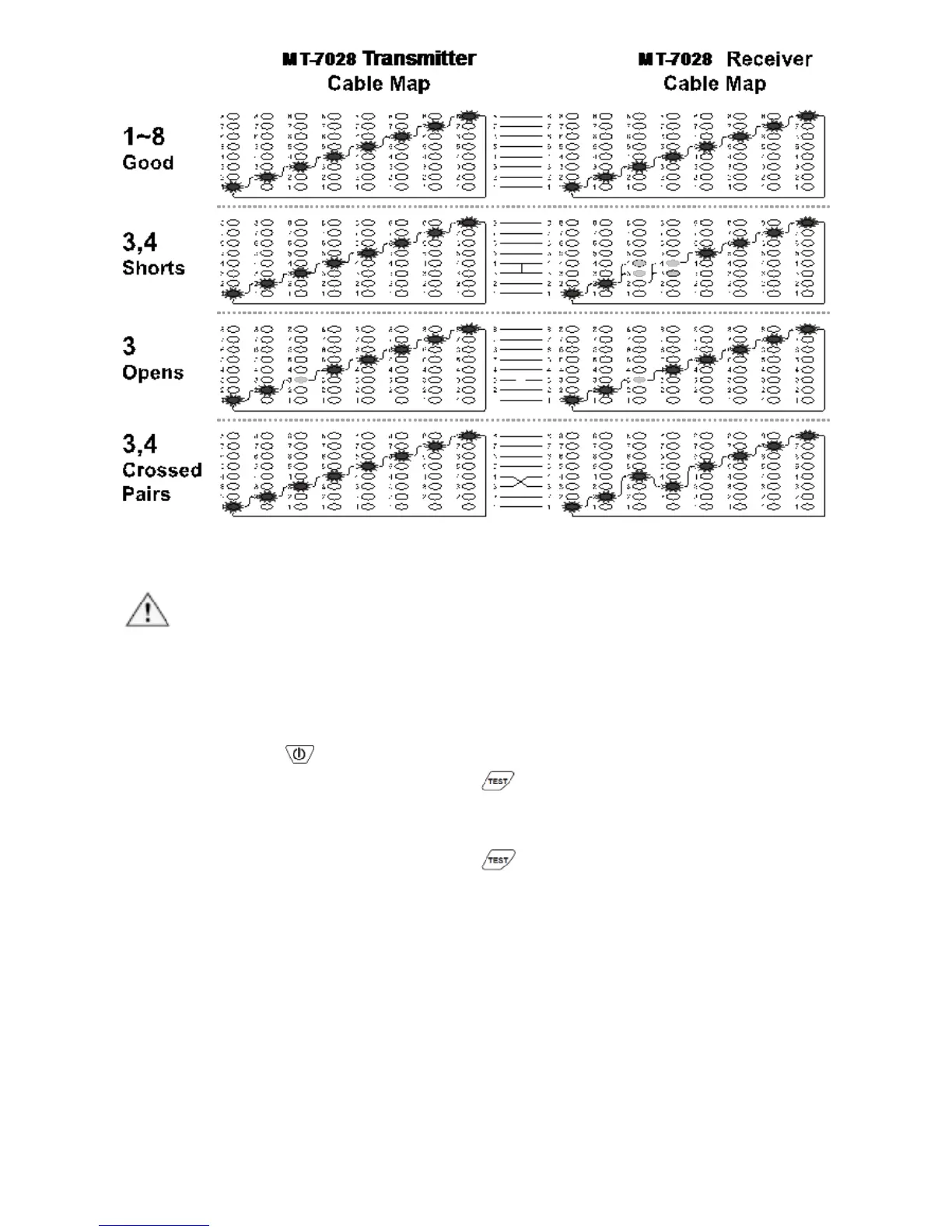
Figure 5 good wiring, shorts, opens, crossed pairs
5. Live telecommunication equipment and router test:
Caution!
The feature can only be used for testing cable continuity and opens, cannot be
used for cross over and short.
1) Connect MT-7028 transmitter and working router by RJ45 cable
map test socket.
2) Push button to turn on the power, “POWER/ BAT LOW”
indicator will light up. Push button on transmitter to feature
cable map function. When the TEST indication green LED flickers
slowly, the slow cable mapping is working and the red cable map
LED starts scanning. Push button again, the TEST indication
green LED twinkles fast, the fast cable mapping is working and the
cable map LED starts scanning. Push the button again, the TEST
green LED light will be off and the product will be standby for next
operation.
3) When the “1~8, G” LED indicator on MT-7028 transmitter lighted
one by one, the cable (1~8, G) is good. If any of LED indicators is
not lighted, the cable is damaged.