ARC 656
PRO
WELD
9
. Be sure to provide proper ventilation when welding in a
confined area.
10. Never look at the electric arc without wearing pr
otective
eye shields.
11. Always use the proper protective clothing, gloves, etc.
12. Never strike an arc when near a bystander who is u
n-
aware of the dangers of ultraviolet light to their eyes.
4.2 Power Supply Safety Precautions
1.
Always connect the frame to t
he power supply to ground
in accordance with the National Electrical Code and the
manufacturer’s recommendations.
2.
Installati
on, servicing, or trouble shooting should be done
by qualified personnel trained to work on this type of equi
p-
ment.
3.
Before servicing this piece of equipment, turn off the di
s-
connect switch at the fuse box.
4.
When in operation, all the covers must be on the equi
p-
ment.
5.0 GENERAL DESCRIPTION
THE PROCESS
Stud welding is a time saving tool which semi
-
automatically
arc welds the FULL
CROSS
-
SECTION of a weld stud to the
base material in a fraction of a second and develops superior
strength over normal arc weldi
ng procedures.
THE UNIT
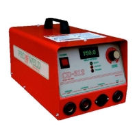
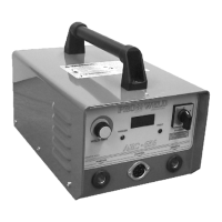
The
ARC
-
656
is a compact , lightweight stud welding power
supply capable of welding studs through 1/2” diameter r
e-
duced weld base. The power supply which operates on three
phase power produces a smooth, stable welding arc. The
front panel dig
ital display indicates the weld time which is
adjustable from .005 to 1.000 seconds. The weld current
which is not adjustable an
d is 650 amps only when using the
standard cable set which is supplied the welder.
6.0 ELECTRICAL INPUT REQUIREMENT
This weldi
ng power source is designed to be operated from
230v, 460v, or 575v three
-
phase, 60 Hertz, AC power Co
n-
sult the local electric utility if there is any question about the
type of electrical system available at the installation site
or
how proper connections to the welding power source are to
PAGE 2
The power unit should be operated from a separately fused or
circuit breaker protected circuit.
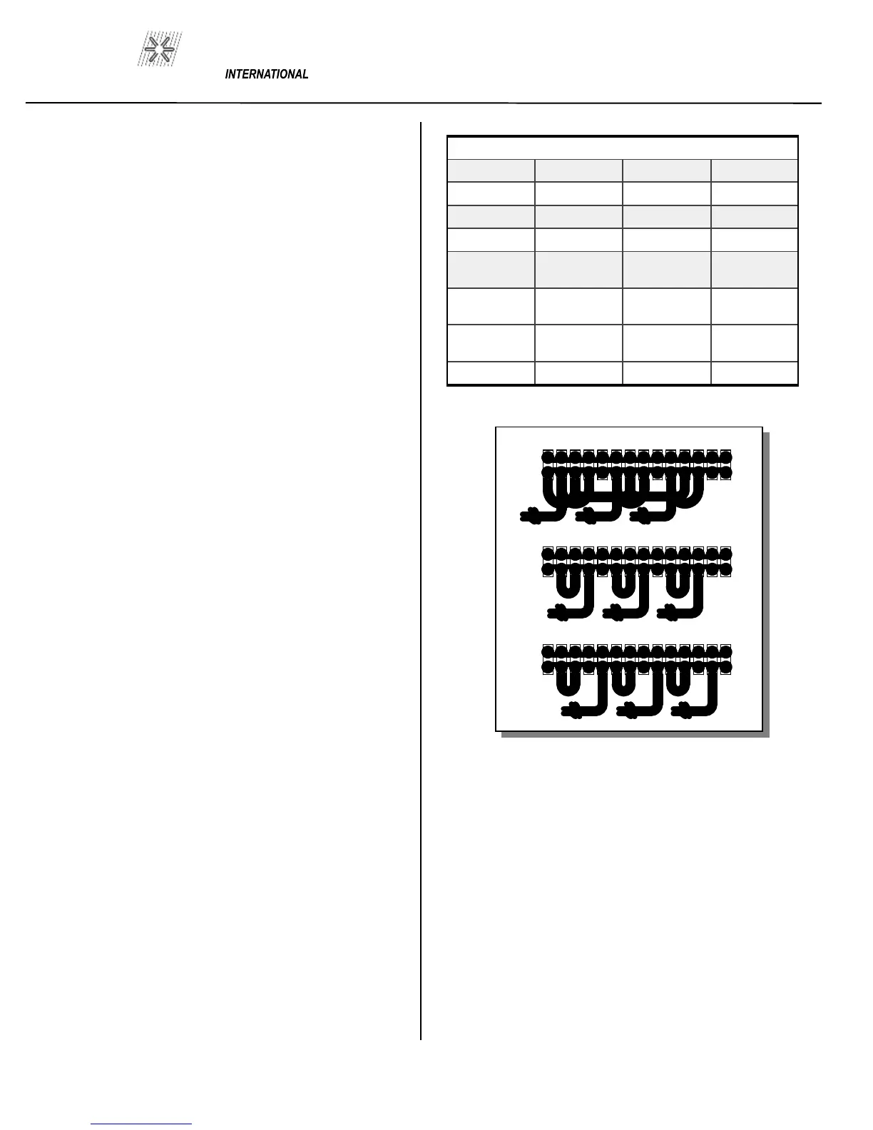
Install three primary leads plu
s one ground wire (see
FIG. 1
)
for proper wire and fuse sizes) through the inlet hole in the
rear of the unit.
The primary cable
s connect to terminals labeled L or LINE.
A FOURTH LEAD (GROUND CONNECTION) SHOULD
BE FASTENED TO THE BOLT LABELED GND. (see
FIG 2 ON NEXT PAGE
) The other end of the ground lead
or cable should be attached to a suitable ground such as a
water pipe, gro
und rod, etc. Use whatever grounding means
is acceptable to the local electrical inspection authorities.
Voltage
230
460 575
L1
2 4 5
L2
6 8 9
L3
10
12
13
Jumpers
1-3-7-
11,
2-
4,6
-
8,10
-
12
2-
3,6
-
7,10
-
11
2-
3,6
-
7,10
-
11
Delay Fuse
Size, Amp
60
30
30
Primary Connection
Primary Wire
Size
-
AWG
#8
#10 #10
Ground Wire
#10
#10 #10
1
2 3 4 5 6 7 8 9 10 11 12 13 14
L1 L2 L3
1
2 3 4 5 6 7 8 9 10 11 12 13 14
L1 L2 L3
1
2 3 4 5 6 7 8 9 10 11 12 13 14
L1 L2 L3
230
575
460
FIGURE 1


 To Next Page