EasyManua.ls Logo

Process Technology DE20 User Manual

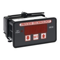
Process Technology DE20
8 pages
To Next Page IconTo Next Page
Page #1 background imageLoading...
Page #1 background image
DE20 Instruction Manual
TABLE OF CONTENTS
DE20 Digital Temperature Control
7010 Lindsay Drive • Mentor, Ohio 44060 • Phone: 440-974-1300
USA/CN: 800-621-1998 • Fax: 440-974-9561 • www.process-technology.com
Specifications....................................................................1
General Description.........................................................2
Installation Procedure.....................................................2
Overtemperature Protection...........................................3
Set Point & Features.........................................................4
Alarm Feature.....................................................................4
Error Conditions................................................................4
Error Messages.................................................................4
Power and Relay Wiring....................................................5
2 Wire RTD Sensor Calibration.......................................6
Resistance Signal Calibration.......................................7
3 Wire RTD Calibration..................................................7
Thermocouple Calibration.............................................8
Voltage Signal Calibration..............................................8
Current Input Calibration.................................................9
Frequency Signal Calibration.....................................10
Configuration (Setup)....................................................10
Main Menu Summary.....................................................10
Sensor Type (U1).............................................................11
Signal Offset (U2)...........................................................11
Signal Filter Setting (U4)..................................................11
Set Point Dead Band (U5) .........................................12
Display Stabilizer (U8)...................................................12
Set Point Limit (L)..........................................................12
Heating or Cooling Switch (F2).....................................12
Alarm On/Off Switch (F3)..............................................13
Unit Display Enable (F4)..................................................13
Temperature Units Conversion (F5)............................13
Sensor DIP Switch Settings........................................13
Electrical Noise and Interference.................................13
Illustration of a Typical Heater Installation in a
Process Tank ...................................................................14
M-33-01-02 02/17/11
Question and Answer IconNeed help?

Do you have a question about the Process Technology DE20 and is the answer not in the manual?

Process Technology DE20 Specifications

General IconGeneral
BrandProcess Technology
ModelDE20
CategoryTemperature Controller
LanguageEnglish

Summary

DE20 Specifications

Description

F3, Alarm On/Off Switch

Parameter to enable/disable the alarm set point functionality. Default is zero (0) for off.

F4, Unit Display Enable Flag

Flag to enable display of C or F units, separated by a decimal point. Units not shown if temp > 999.

F5, Temperature Units Conversion

Setting to display temperature in Fahrenheit (0) or Celsius (1). Does not change set point values.

F6, Current Output Enable Flag

Parameter related to the current output control.

Sensor DIP Switch Settings

Configuration settings for sensor type via DIP switches on the 5415 board.

Installation

Overtemperature Protection

Component failure can cause damage, fire, or hazardous conditions. Install overtemperature protection.

Set Point and Features

Control Set Point

Procedure to view and change the set point value using the SET, DECREASE, and INCREASE keys.

Alarm Feature

Allows setting a point above which the control enters an alarm condition, de-energizing the relay.

Error Conditions

Describes sensor values out of range or open/short circuits causing 'HHH' or 'UUU' error displays.

Error Messages

Indicates potential corruption of calibration/configuration data with 'c' or 'C' on the display.

Configuration

Main Menu Summary

Summary of DE20 parameters (U1-U8, L, F1-F5) and their functions.

Power and Relay Wiring

Procedure for connecting power supply, set point relay, and sensor to the controller.

Calibration Procedures

Current Input Calibration

Steps to restore, update, or verify standard values for DC current measurement.

2 Wire RTD Sensor Calibration

Procedure to calibrate the DE20 for 2-wire RTD sensors using precision resistors.

Resistance Signal

Procedure for measuring pure resistance, similar to 2-wire RTD calibration.

3 Wire RTD Sensor

Procedure to calibrate the DE20 for 3-wire RTD sensors using precision resistors.

Thermocouple

Procedure to calibrate the DE20 for thermocouple sensors using a calibrator.

Voltage Signal Calibration

Steps to restore, update, or verify standard values for DC voltage measurement.

Related product manuals