EasyManua.ls Logo

Procom DGC-202 Series - User Manual

Procom DGC-202 Series
40 pages
Print Icon
To Next Page IconTo Next Page
Loading...
PR C MO O
®
Installation Guide
Rev.-01
OPERATING INSTRUCTIONS
DGC-202X
Question and Answer IconNeed help?

Do you have a question about the Procom DGC-202 Series and is the answer not in the manual?

Overview

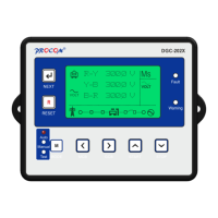
The DGC-202X Series modules are advanced generator controllers designed for both manual and automatic operation of generator sets. They automatically start and stop the generator based on the status of the mains (utility) supply and facilitate load transfer to the generator. The modules also offer a "Test Mode" for easy debugging during genset building and testing. They monitor the engine's operational status, automatically shutting down the engine and indicating faults and warnings on an LCD display.

Function Description:

The DGC-202X modules provide comprehensive control and monitoring for generator sets. They are capable of:

  • Automatic Operation: Starting and stopping the generator based on mains supply status, transferring load, and shutting down after cooling when mains are restored.
  • Manual Operation: Allowing operators to manually start and stop the engine, with automatic load transfer and protection functions.
  • Engine Monitoring: Tracking various engine parameters and shutting down the engine upon detection of faulty conditions.
  • Fault and Warning Indication: Displaying operational status, faults, and warnings on an LCD.
  • Load Transfer: Managing the transfer of electrical load between the mains and the generator.
  • Protection: Implementing various protections against unhealthy conditions in both the generator and mains supply.

Important Technical Specifications:

  • Power Supply:
    • Minimum Supply Voltage: 8V continuous
    • Maximum Supply Voltage: 35V continuous
    • Cranking Dropouts: Survives 0V for 400ms (provided supply was ≥10V before dropout and recovers to ≥5V afterwards).
    • Maximum Operating Current: Varies from 58mA (12V, backlight on) to 74mA (24V, all sensors connected).
    • Maximum Standby Current (LCD backlight off): 47mA (24V) / 51mA (12V).
    • Maximum Sleep Mode Current: 35mA (12V) / 32mA (24V).
  • Battery Voltage Display:
    • Range: 0V-40V DC
    • Resolution: 0.1V
    • Accuracy: 1% of Reading + 1 Least Count (at 12V 0.2V).
  • Generator Voltage/Frequency Sensing:
    • Measurement Type: True RMS conversion (up to 11 harmonics).
    • Input Impedance: 300K Ph-N.
    • Measurement Range: 30V to 330V AC (Phase to Neutral), 50V to 570V AC (Phase to Phase).
    • Common Mode Offset from Earth: 100V AC (max).
    • Resolution: 0.1V.
    • Accuracy: ±1% of Reading (phase to neutral), ±1% of Reading (phase to phase).
    • Frequency Range: 15.0Hz to 75.0Hz.
    • Frequency Resolution: 0.1Hz.
    • Frequency Accuracy: ±0.05Hz.
  • Generator Current Sensing:
    • Measurement Type: True RMS conversion (up to 11th harmonic).
    • Nominal CT Secondary Rating: 5A.
    • Maximum Continuous Current: 10A.
    • Absolute Maximum Overload: 50A for 1 second.
    • Burden: 0.25VA (0.01E current shunts).
    • Resolution: 0.5% of 5A.
    • Accuracy: ±1% of Nominal (excluding CT error).
  • Digital Inputs: 6 fully configurable, connection to ground, programmable as Normally Open or Closed.
  • Analog Inputs (Coolant Temperature, Fuel, Pressure): Resistance measurement by measuring voltage across sensor with a fixed current applied. Differential resistance measurement input.
    • Measurement Current: 13mA independent of System Voltage.
    • Full Scale: 600 Ohms.
    • Resolution: Fuel 1%, Temperature 1°, Pressure 0.1 bar.
    • Accuracy: <1% of Full scale ± 4 Ω (excluding transducer errors).
    • 4-20mA Pressure Sensor Interface: Burden of 100 Ω, 2% accuracy (excluding transducer error).
  • Charging Alternator Interface:
    • Excitation Current: 220mA @12V (Typical), 110mA @24V (Typical).
    • Measurement Range: 0-40V.
    • Accuracy: 1% of reading.
    • Resolution: 0.1V.
  • MPU Input:
    • Frequency Range: 5Hz - 7.5KHz.
    • Load: 10K Ω.
    • Voltage Input: 3V (Min), 40V (Max).
    • Input Wave Form: Square.
    • Input From: Magnetic Pickup Unit (MPU) or Charging Alternator W point.
  • Digital Outputs: 6 outputs, 400mA drive current, delivers System Voltage. Protected against Over Temperature, Short Circuit, Over current, and Load Dump.
  • Communication Ports:
    • USB 2.0: For programming, reading parameters, fault history, event recordings. Uses Type A to Type B cable.
    • CAN (J1939): 250K, Non-Isolated, Internal Termination of 120 Ω.
    • RS485: Fully Isolated and Protected against 200V, Isolation voltage 4KV, Modbus Implemented, Internal Termination of 120 Ω.
  • Display: 128x64 pixels Graphical LCD Display with Icon and English Text Based Descriptions.
  • Environmental:
    • AC Voltage Withstand: 450 VAC (Phase to neutral).
    • Surge: 2.5KV (1.2/50Usec).
    • Operating Temperature: -20°C to 70°C.
    • Storage Temperature: -30°C to 85°C.
    • Vibration: 5Hz - 8Hz at +/- 7.5mm, 8Hz - 500Hz 2g.
    • IP Rating: IP65 (from front).

Usage Features:

  • User-Friendly Interface: Icon and English Text Based LCD display for clear understanding of parameters, status, warnings, and faults.
  • Configurable Inputs/Outputs: Digital inputs are fully configurable for various alarms and functions. Digital outputs can be assigned to functions like Unit Healthy, Glow Plug/Choke, Fuel Pump, Load Warning, and MCCB Shunt Trip.
  • System Configuration: Configurable for different mains and generator phase connections (Single Phase Mains/Gen, Three Phase Mains/Single Phase Gen, Three Phase Mains/Gen).
  • Sensor Flexibility: Built-in sensor data and provision to program user-defined sensor data for temperature, pressure, and fuel. Supports 4-20mA pressure sensors.
  • Fuel Solenoid Configuration: Can be set as "Pull to Start" or "Pull to Stop."
  • Password Protection: Access to program/modify parameters via front keys is password protected.
  • Auto Scroll Display: Parameters automatically scroll every 10 seconds, or the "Next" key can be pressed to view the next parameter window.
  • Backlight Management: Backlight brightness adjusts based on activity (100% on key press/fault/warning, reduced to programmed level after 120 seconds of inactivity, off during cranking).
  • Remote Start/Stop: Digital inputs can be assigned for remote start/stop functionality in manual mode.
  • Mode Selection: Front keys or a digital input can select between Auto, Manual, and Test modes.
  • Fault History and Event Records: Stores the last 64 faults and events with time stamping, viewable on the LCD or downloadable via USB/RS485.

Maintenance Features:

  • Service Due Hour: Tracks remaining hours until the next service is due, acting as a warning/reminder.
  • Reset Service Alarm: Allows resetting the service due hour.
  • Lamp Test: All LEDs blink when the reset switch is pressed during power-up, allowing for quick verification of LED functionality.
  • Firmware Updates: USB communication allows for programming the controller, suggesting potential for firmware updates.
  • Parameter Adjustment: All parameters can be changed from the front panel, via USB, or RS485 communication, facilitating easy maintenance and customization.

Procom DGC-202 Series Specifications

General IconGeneral
BrandProcom
ModelDGC-202 Series
CategoryController
LanguageEnglish

Related product manuals